17
Connection Diagrams
Below are three common configurations to utilize the contents of the Evaluation Kit. Terminal
block (P2) or Molex PicoBlade™ connector (P3) allow the user to connect an independent power
supply (e.g. battery, bench-top supply) or the rectified output of the AC Power Cell as the input
power source of the attached load or device as shown in Figure 11.
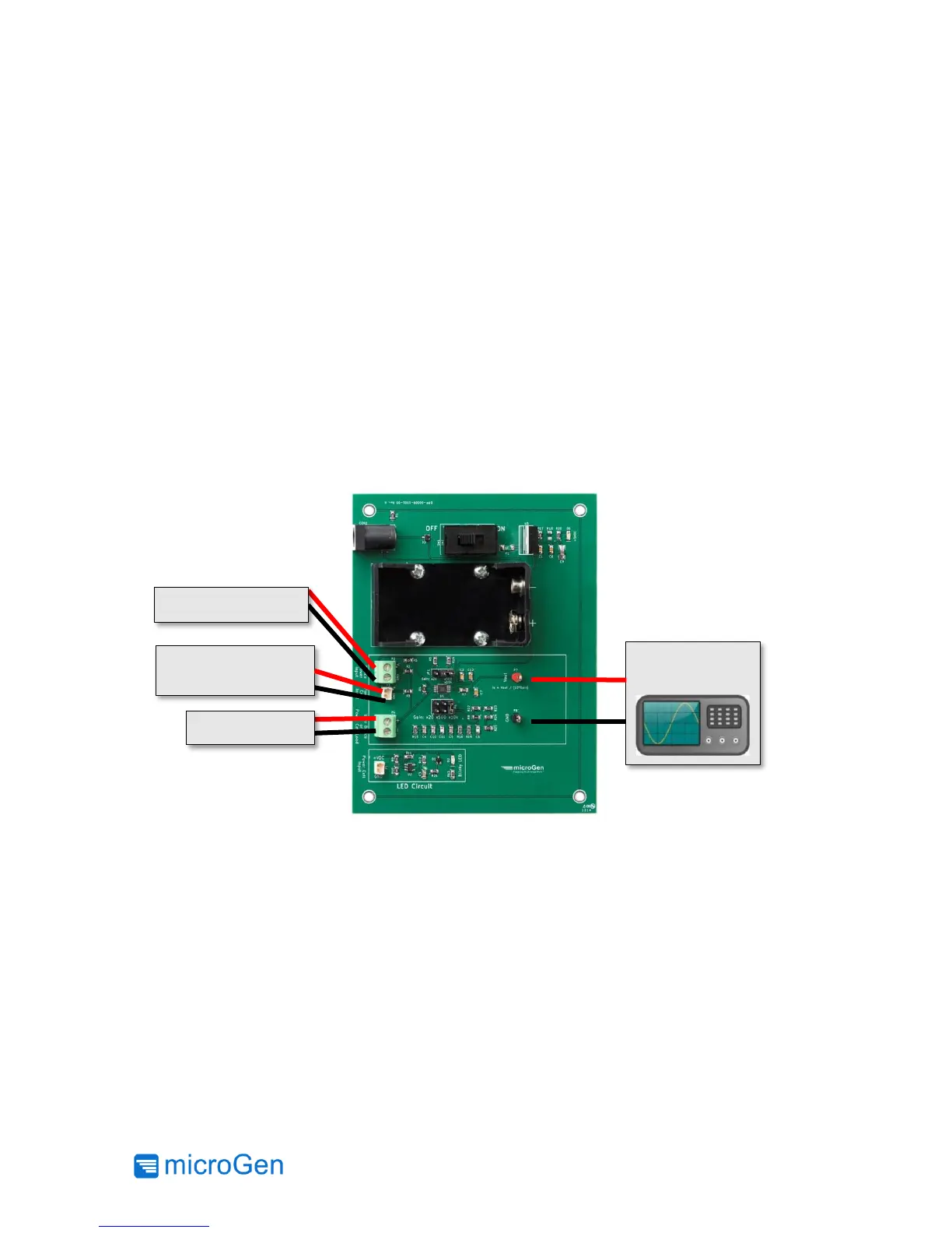
To characterize the energy harvested from the AC Power Cell and the user’s vibrational source
use Figure 12. To properly measure the power generated a load must be used (e.g. 150K Ohm
resistor).
The Blinking LED Test Circuit may be used as a load for the rectified output of the AC Power Cell
when connected as shown in Figure 13. Also the LED provides a quick visual confirmation that
energy is being harvested
Figure 11: Measuring Current Draw of a Device from a Power Source