16
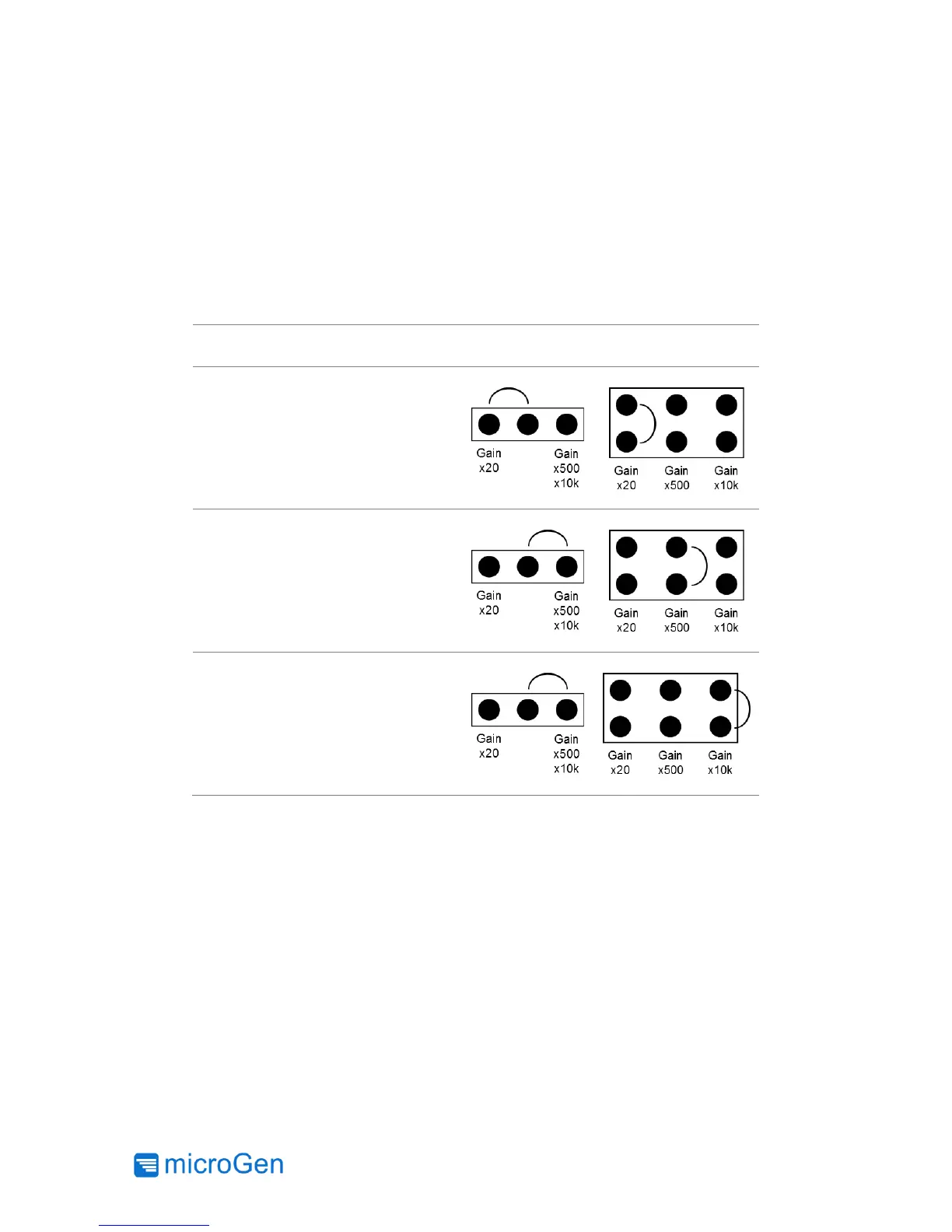
Gain Jumper Configurations
The Current Sense Circuit is able to measure current over a wide range (10 µA to 25 mA).
However, the full range is binned into three groups to ensure complete coverage of the current
sensing range. See Table for the gain jumper configurations. Note any configuration not show in
Table 7 is invalid.
Table 7: Gain Configurations
Blinking LED Test Circuit
The Diagnostic Board also contains a Blinking LED Test Circuit. This test circuit is primarily used
as a quick indicator that DC output is being generated from the AC Power Cell rectified and
conditioned by a Power Management Board, but it can also be used as a test load for the Current
Sense Circuit. Use the configuration Figure 13 in the Connections Diagrams section.