6
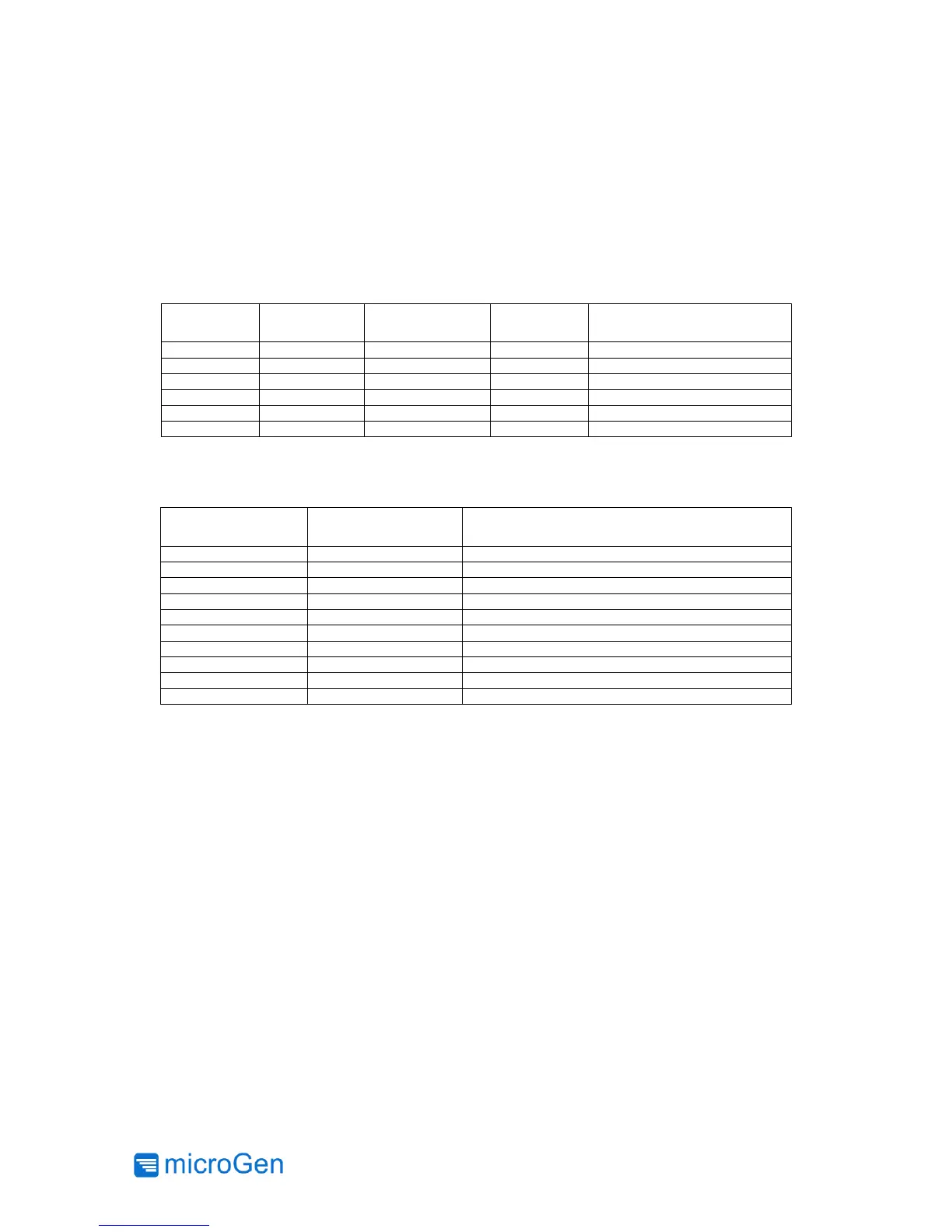
AC Power Cell Board Components
The AC Power Cell board contains the AC Power Generator, located at the center of the board,
and two 3-pin headers for connecting accessory boards (e.g. microGen’s Power Management
Boards) on top of the AC Power Cell, or the user’s custom electronics. Also included on the board
are configuration resistors that route the power signals, and loops for probe clips should the need
arise to view the harvester voltage output.
Connect -HV1 to output P1
Connect screw holes to ground
Connect +HV1 to output P1
* Not used in standard single AC Power Cell configuration
Table 2: AC Power Cell board components
Mounting
It is essential to mount the AC Power Cell to the vibration source as securely as possible to ensure
vibrations are efficiently transferred to the AC Power Generator. The PCB has (4) mounting holes
to accommodate a standard #4-40 machine screw. Other methods of coupling, such as a strong
magnet, can also be used, as long as the AC Power Cell remains fixed and attached to the surface
of interest. Mounting hole locations can be seen on Figure 17 in the appendix.