9
Configurations
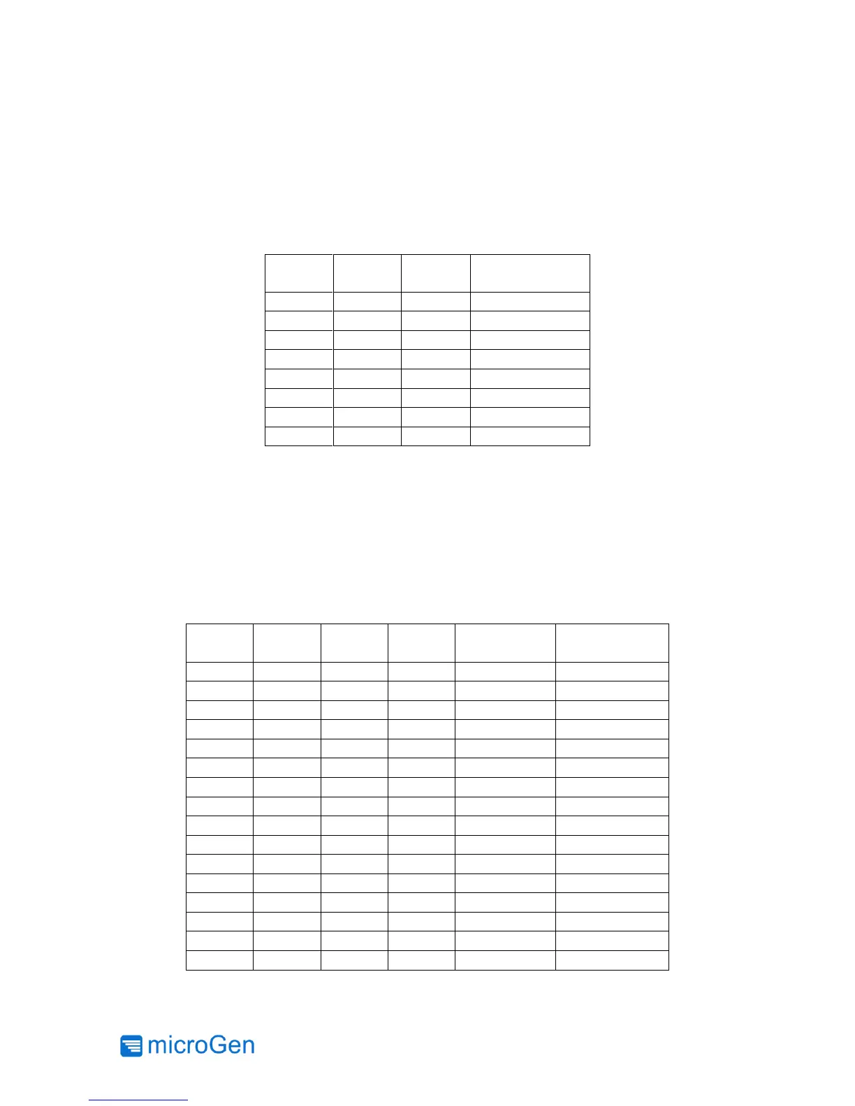
The output voltage of the LTC3330 Power Management Board is configurable by the user. Use
the provided VOUT jumpers and Table 4 for proper configuration. Note that the LTC3330 only
operates in DC/DC Buck Mode so the output voltage cannot equal to or greater than the user
configured harvesting input voltage.
Table 4: Output Voltage Configurations
Depending on the strength of the vibration, there may be an optimum input voltage range to
harvest from. Table 5 shows the configurations available. If using the harvester in resonant mode,
it is recommended that the harvesting voltage range chosen encompass a voltage approximately
½ the peak AC voltage generated by the harvester WITHOUT loading (the “open circuit” voltage).
If using the harvester in impulse mode, typically the lowest voltage range is chosen that can still
provide the desired output voltage (e.g., to use the 3.3V output setting, the lowest usable range
is the 4-5V range since this chip uses a buck regulator).