Quick Start Guide
Commissioning the
28-Port 10G Multi Fiber L2/L3 Switch 19"
4 MICROSENS GmbH & Co. KG, Kueferstr. 16, 59067 Hamm, Germany
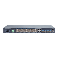
2 Display and Connections
Fig. 1: Display and Connections
Main power supply (100-240 VAC,
standard module)
Redundant power supply (100-240 VAC,
optional module)
Ethernet management port (OOB)
LED indicators (PWR1, PWR2, ports status LEDs)
3 Mounting the Device
This device supports two installation methods:
Rack mounted installation
Desktop installation
Note:
All necessary mounting parts are provided with the enclosed mounting accessory set.
3.1 Rack Mounted Installation
Please follow the steps below:
1. Fix the provided rack mounted hangers to the left and right side of the device using 4 screws each. Use
the four holes on the left and right side of the device.
2. Install the device to the rack.
Keep the following points in mind:
Make sure not to pinch existing cables!
Keep a distance of at least 5 cm to nearby devices to provide ventilation and to avoid overheating.