Quick Start Guide
Commissioning the
28-Port 10G Multi Fiber L2/L3 Switch 19"
10 MICROSENS GmbH & Co. KG, Kueferstr. 16, 59067 Hamm, Germany
o Green – The respective power supply is working.
7.2 Port Status LEDs
7.2.1 Ethernet (10/100/1000Base-T)
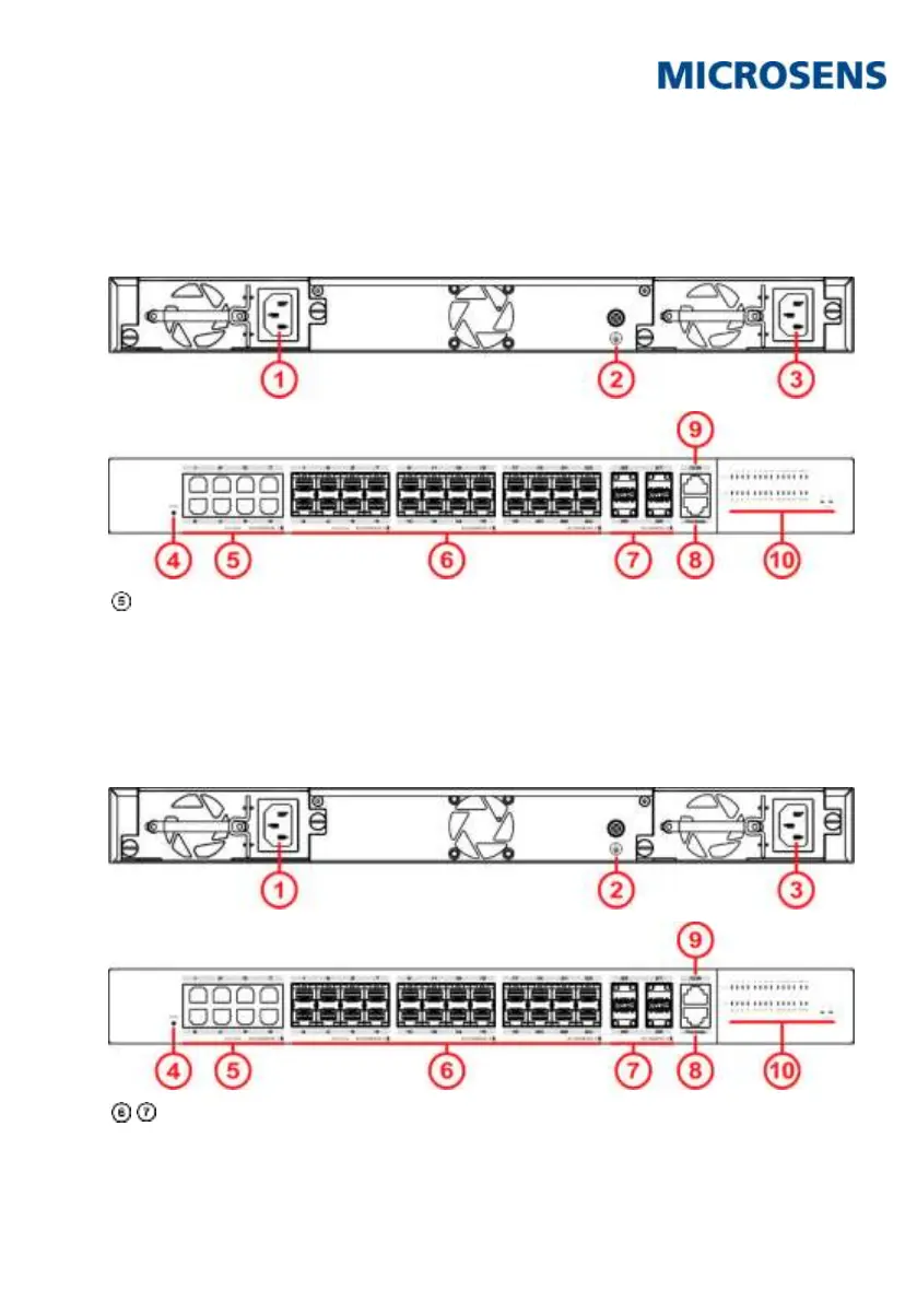
The device’s Ethernet copper ports (s.
Fig. 1, ) have one port status indicators
Port link indicator
o Off ‒ Link down, no connection.
o Green ‒ Link up
o Green blinking ‒ Port sending or receiving data.
7.2.2 SFP/SFP+ (1000Base-X and 1000/10GBase-X)
The device’s SFP and SFP+ ports s.
Fig. 1,
) have one port status indicator:
lnk (Link)
o Off ‒ Link down, no connection.