Quick Start Guide
Commissioning the
28-Port 10G Multi Fiber L2/L3 Switch 19"
11 MICROSENS GmbH & Co. KG, Kueferstr. 16, 59067 Hamm, Germany
o Green ‒ Link up
o Green blinking ‒ Port sending or receiving data.
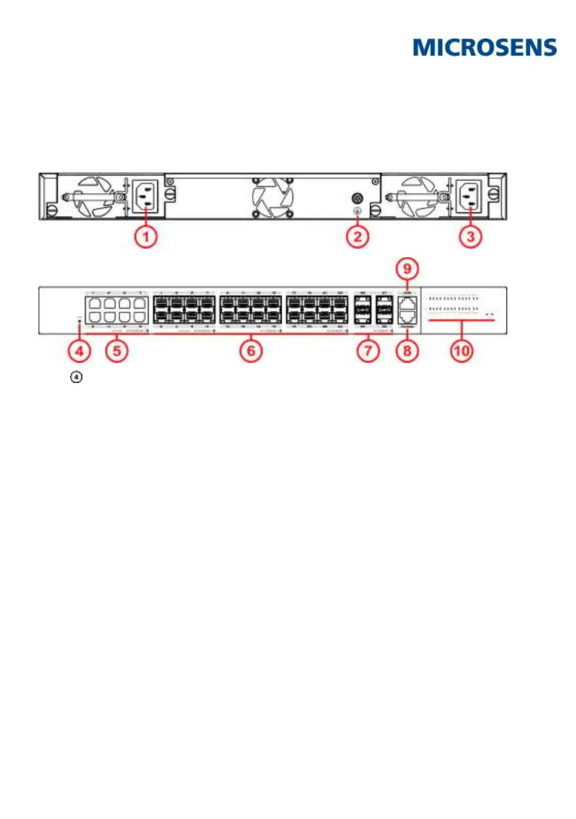
8 Reset Button
On the front of the housing there is a reset button (s.
Fig. 1, ), which is accessible with a thin object.
By pressing the button longer than 5s, the switch will be restored to the original factory default setting.
Note:
Additionally, status messages are issued via the console port.
9 Access for Network Management
Note:
For accessing the device after starting up successfully please refer to one of the following documents:
Web manual: describes Web network management system configuration instructions.
CLI manual: describes CLI-based configuration instructions
10 Firmware Updates and Further Information
You have access to current firmware versions and further information once you have registered on our website.
10.1 Registration
1. In your internet browser open the address “www.microsens.com” and navigate to the page “Partner
Login”.
2. Follow the link “Please register here”.
3. Fill out and submit the online user registration form.
4. You will receive an e-mail containing a user name and password for the partner login.
10.2 Login
1. In your internet browser open the address “www.microsens.com” and navigate to the page “Partner
Login”.
2. Enter your username and your password.
3. Click the button “Login”.