24 Port Gigabit Ethernet PoE Switch – User Manual Page 19 of 72
________________________________________________________________________
©2014 MICROSENS GmbH & Co. KG – Hamm/Germany www.microsens.com
3-1-1. Page Layout
On the top part of the information page, it shows the front panel of the switch.
Linked ports will be displayed in green color, and linked-off ones will be in black. For the
optional modules, the slots with no module will only show covered plates, the other slots
with installed modules would present modules. The images of modules would depend on
the ones you insert. Vice versa, if ports are disconnected, they will show just in black.
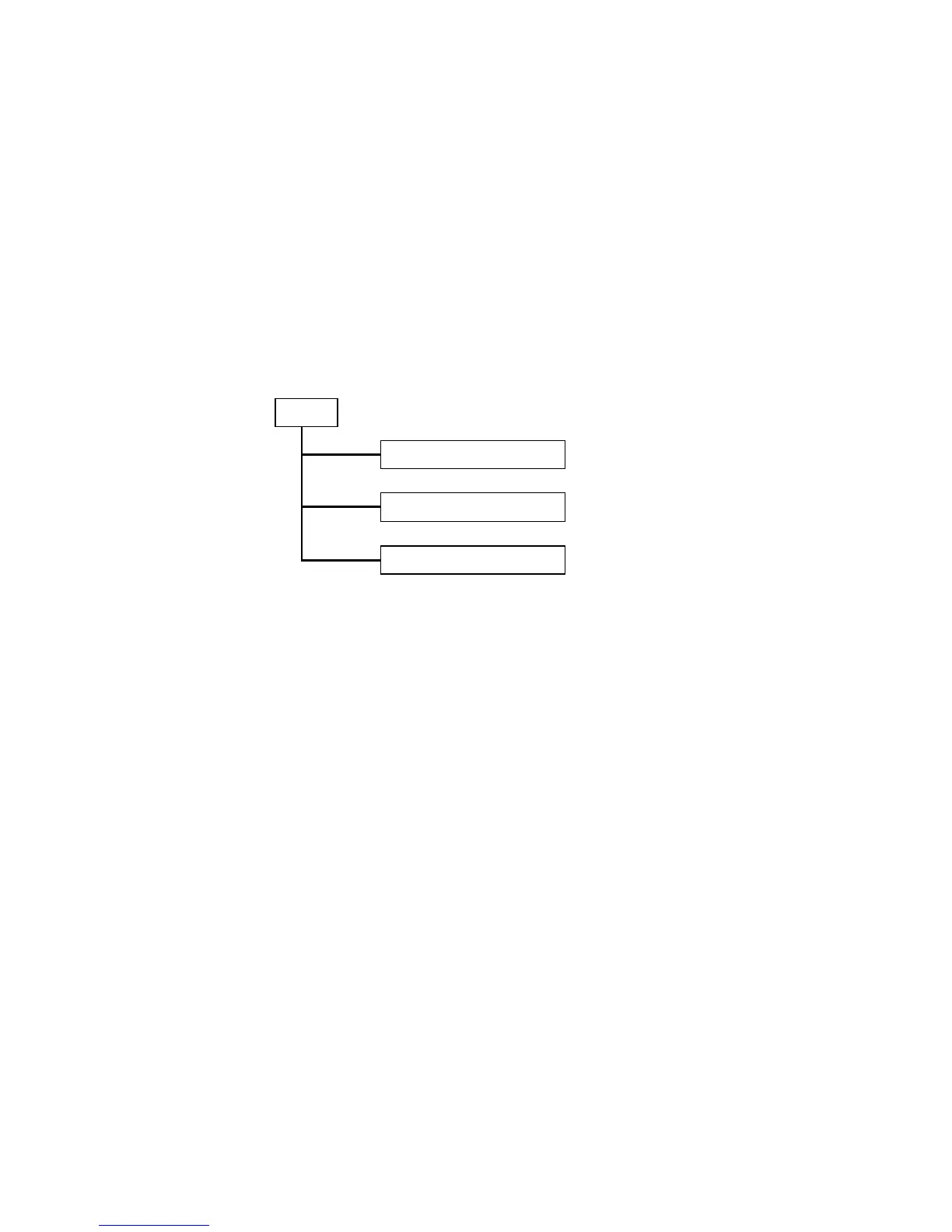
On the left side, the main menu tree for web is listed in the page. According to the
function name in boldface, all functions can be divided into three parts, including “Con-
figuration”, “Monitoring” and “Maintenance”. The functions of each folder are described in
its corresponded section respectively. As to the function names in normal type are the
sub-functions. When clicking it, the function is performed. The following list is the main
function tree for web user interface.
 Loading...