is located in a tight or separate room, additional ventilation
may be required. Install two permanently open grills, each
sized on the basis of one square inch free area per 1,000
BTU (but not less than 100 square inches) of the total input
rating of all gas utilization equipment located in the
confined space. One grille should be located within 12"
inches of the ceiling, the other within 12" of the floor.
If the gas utilization equipment is located in an area of
unusually tight construction, or if an exhaust fan, kitchen
ventilation system, clothes dryer and/or fireplace is installed
in the building, provisions must be made for an outside air
supply near the gas utilization equipment area. Install
permanently open grills sized at not less than one square
inch free area per 4,000 BTU of burner input. When
ventilating through horizontal ducts, grills should be sized
not less than one square inch free area per 2,000 BTU. In
any case, the minimum dimension of rectangular air ducts
shall not be less than 3 inches.
In Canada, for detailed ventilation requirements, refer
to standard CAN/CGA 1-B149.1 or .2 and/or local codes.
___________________________
II - Preparation of the Gas Utilization Equipment
Clean the appliance, heat exchanger interior,
combustion chamber, and flue connections. Remove all
adhering tars, scale, dirt and soot. Inspect for actual leaks
and/or potential leaks.
Cement all joints, including those in the gas utilization
equipment base and around door frames, to prevent
Part 1 Installation
Specifications
NATURAL or PROPANE Gas
Air Delivery
(Approximate air delivery at zero draft)
Maximum Firing Rate**
Minimum Firing Rate**
Tube Diameter
Tube Length
Combustion Chamber Size
100 MBH ***
200 MBH ***
300 MBH ***
Gas Pressure Required
NATURAL or PROPANE
Electrical Supply Standard
Flame Safety
Main Automatic Valve
EC 200 EC 300
40.0 SCFM* 60.0 SCFM*
200 MBH*** 300 MBH***
70 MBH*** 90 MBH***
4 inches 4 inches
7.50 inches 7.50 inches
Recommended Minimum W & H
8" W x 8" H
10" W x 10" H
14" W x 14" H
6.0" to 14.0" W.C. 6.0" to 14.0" W.C.
120/1/60, 2.0 Amps 120/1/60, 3.0 Amps
230 volts 50/60 hz **** 230 volts 50/60 hz ****
24V Electronic Flame Safety, with 100% shut-off, 30-
second pre-purge.
3 Function Redundant 3 Function Redundant
General information
CAUTION: The ECONOMITE EC Series is not intended for
outdoor installation and must be protected from excessive
moisture. Provide adequate clearance for service and proper
operation.
___________________________
Before installation, read these instructions carefully.
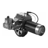
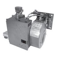
The EC 200 / 300 burner is a gas power burner designed for
firing natural or propane gas in most applications. The burner is
a self-contained unit consisting of a blower assembly, burner
head, ignition control and a combination gas valve. The burner
installation involves mounting the burner to the gas utilization
equipment, piping the gas train and connecting the power
supply. Every burner is operationally fire tested at the factory
prior to shipping.
___________________________
I - Ventilation
If the former automatic oil burner provided trouble-free
operation, then the gas utilization equipment area should have
sufficient air for combustion and the dilution of flue gases.
Nevertheless, the area must be checked:
Open basement or utility areas of normal construction,
without storm windows or tight doors, will generally allow
sufficient air infiltration. However, if the gas utilization equipment
2
Notes:
* SCFM=Standard Cubic Feet/Minute
** Ratings based on 1,000 BTU/cu. ft. NATURAL, 2500 BTU/cu. ft. PROPANE at Sea Level.
***1 MBH=1,000 BTU/Hr.
**** Available - Contact Factory
Derate burner for altitudes over 2,000 feet by 4% for each 1,000 feet above sea level.
Midco International Inc. - Chicago IL - www.midcointernational.com