3
Part 1 Installation
leakage into or out of the combustion chamber.
The access or firing door should open easily to relieve
pressure. If positive latches exist, they should be modified
to permit easy opening; a spring loaded door holder is
recommended.
On all boilers, make certain the pressure relief safety
valve is in good operating condition.
___________________________
III - Combustion Chamber
A combustion chamber liner is normally required to protect
non-heat transfer surfaces and to provide a radiant bed for
rapid heat transfer to the primary surfaces of the heat
exchanger. In most cases, an existing oil burner
combustion chamber liner can be used, if in good condition.
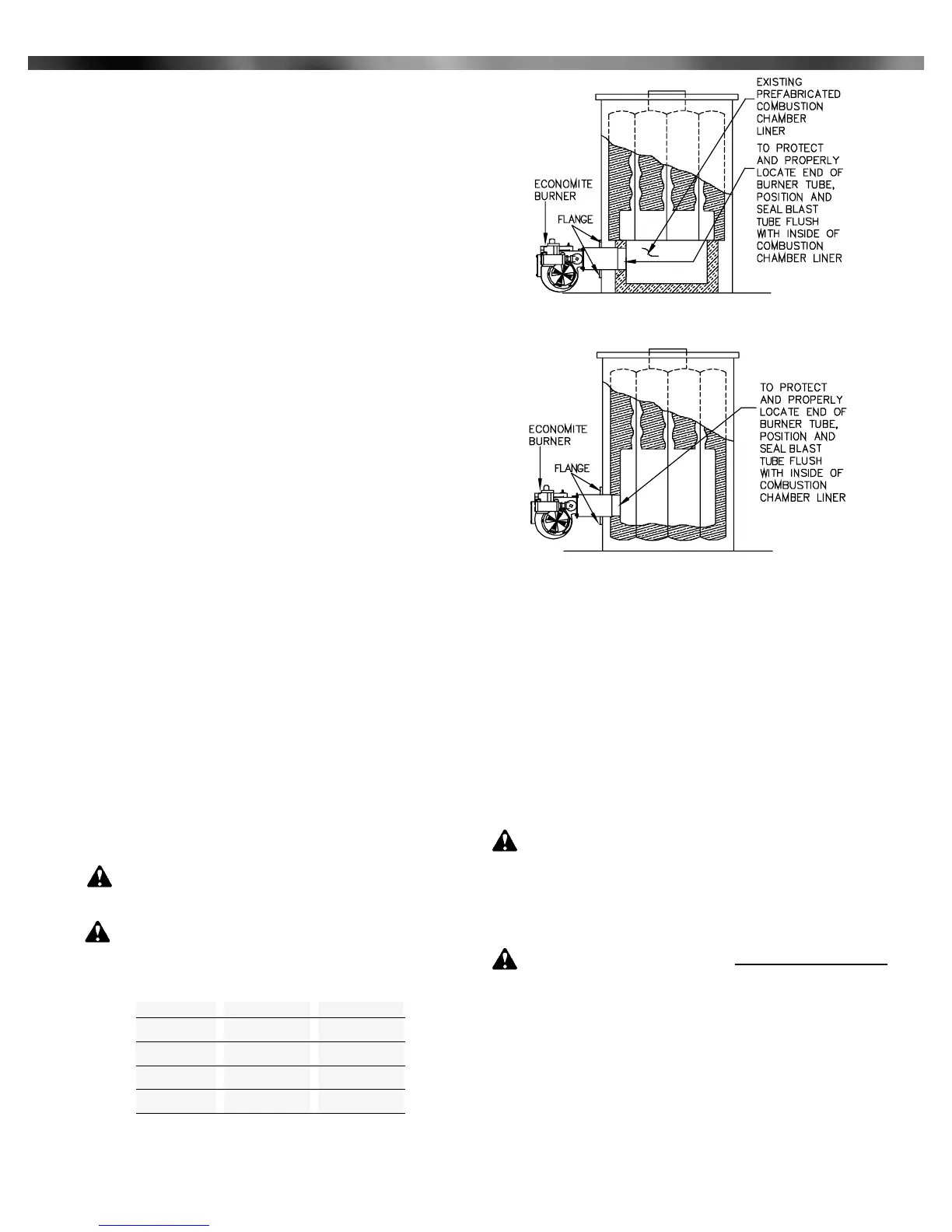
Install mounting flange to the burner blast tube. The
distance from the flange to the blast tube edge should be
same as the gas utilization equipment wall thickness plus
the flange gasket thickness. This will allow the burner blast
tube to be flush with the inner chamber wall after the burner
is installed. If the blast tube extends into the combustion
chamber serious damage to the burner may occur, voiding
the warranty, see Figure 1 & 2 for reference. For minimum
combustion chamber dimensions see Table 1.
Mount the burner to the appliance. Use the supplied
gasket to assure a tight seal between the mounting flange
and front plate gasket.
With a wet base boiler, where the entire combustion
chamber is comprised of heat exchange surfaces and no
combustion chamber liner was provided for oil firing, a liner
is usually not required. A liner or target wall may be
necessary if the combustion chamber is unusually short.
To avoid flame contact on the heat exchanger walls or
flueways.
Use 2300°F minimum insulating material when the
application requires the construction or replacement of a
combustion chamber liner
The burner tube must be sealed air tight into the
combustion chamber liner opening with refractory material
as shown by Figures 1 and 2.
CAUTION: In no case should the burner tube be
allowed to extend into the combustion chamber; it
must be set flush with the inside surface.
WARNING: Burner cabinet must be mounted in
orientation shown in Figures 1 and 2. Any other
mounting may cause a dangerous condition, and will void
burner warranty and agency approvals. Non-standard
arrangements may be available for some models; consult
factory for details if required.
Before permanently setting the burner in place, check that
the burner nozzle is free of foreign materials and that the elec-
trodes have not been damaged or displaced, see Figure 8.
___________________________
IV - Chimney, Vent Connector, and Draft Control
WARNING: The chimney should be inspected for
unsafe conditions such as deteriorated masonry and
excessive soot or other blockage. Installation must
conform with local codes. In the absence of local codes,
the recommendation installation compliance is with ANSI
Z21.8b latest edition and NFPA, ANSI Z223.1 latest edition.
WARNING: The Vent Connector shall not be connected
to a chimney that is venting solid fuel burning from any
equipment, any incinerator or any open fireplace.
The Vent Connector shall be made of non-combustible,
corrosion resistant material capable of withstanding the vent gas
temperature produced by the appliance and of sufficient
thickness to withstand physical damage.
The Vent Connector shall be as short as possible. The
entire length shall be readily accessible for inspection, cleaning
and replacement.
The length of horizontal uninsulated Vent Connector
between chimney and a single gas utilization equipment shall
Figure 1: Dry Base Boiler with Combustion Chamber
Liner (Similar to Warm Air Furnace Construction)
Figure 2: Wet Base Boiler with Combustion Chamber Unlined
Gas Input
MBH* Width/Height "
100
150
200
250
300
8"
9"
10"
10"
10”
Length "
8"
9"
10"
10"
11”
Table 1: Minimum Combustion Chamber Dimensions
* 1 MBH = 1,000 BTU/Hr
Source: ANSI Z21.8b 1993, Installation of Domestic Gas
Conversion Burners. For other applications, consult factory.
Midco International Inc. - Chicago IL - www.midcointernational.com
 Loading...