low voltage (check white and green wire to earth ground)
from other equipment as that can cause the electronic
flame safeguard to malfunction.
Each installation must include suitable limit controls.
The existing oil burner combination limit and operating
controls are NOT SUITABLE for gas burner safety and
operation.
Set the thermostat heat anticipator to the current draw
of the gas burner. The current draw of the gas burner 24V
operating circuit is 0.7 amps.
CAUTION: Label all wires prior to disconnection
when servicing controls. Wiring errors can cause
improper and dangerous operation. Verify proper
operation after servicing.
___________________________
not exceed 75% of the height of the chimney above the
connector, or 100% if the Vent Connector is insulated.
The Vent Connector shall be installed so as to avoid turns
or other construction features which create excessive resistance
to flow of vent gas. It shall be installed without any dips or sags
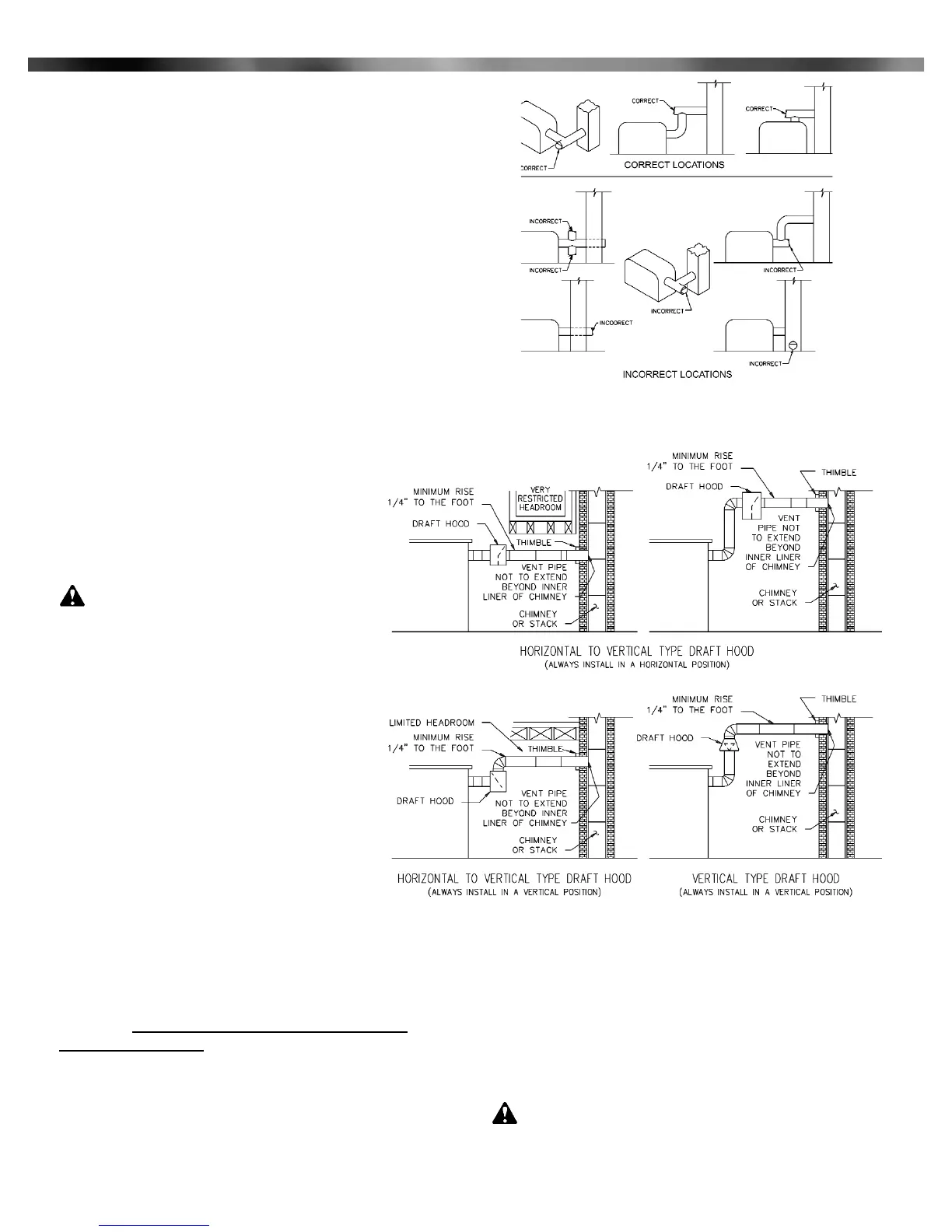
and shall slope upward at least 1/4" per foot.
A manually operated damper shall not be placed in the
Vent Connector or chimney of any gas utilization equipment.
The Vent Connector shall be firmly attached to draft hood
outlets and flue collars. Joints between sections of connector
piping shall be fastened by sheet-metal screws or other
approved fittings. The Vent Connector shall be supported for the
design and weight of the material employed to maintain
clearance and prevent physical damage and separation of
joints.
A draft hood or barometric draft regulator shall be installed
in the same room as the equipment in such a manner as to
prevent any difference in the pressure between the hood or
regulator and the combustion air supply. In no case shall the
relief opening of the draft hood or barometric draft
regulator be located at a point lower than the top of
the highest flue passage in the equipment.
________________________
V - Electrical
CAUTION: Do not add any power
consuming devices in the low voltage circuit to
prevent overloading of the transformer.
Note: If any of the original wiring as supplied with
the conversion burner must be replaced, it must be
replaced with type TFF wire or equivalent.
Installation wiring and grounding of the burner must
conform to local codes, or in their absence in the
United States to National Electric Code,
ANSI/NFPA No. 70-latest edition; in Canada, to
Canadian Electrical Code Part 1, CSA Standard
C22.1.
Electrical installation must be made in
accordance with the United States National Electric
Code, ANSI/NFPA No.70-latest edition or Canadian
Electrical Code, Part 1, CSA Standard C22.1 and
applicable local code. If the burner is a part of a
gas utilization equipment system, check the wiring diagram as
supplied by the manufacturer.
Refer to the wiring diagram Figure 5 or the same wiring
diagram supplied on the inside of the burner wiring enclosure.
There are three leads (black - L1, white - L2 and green -
ground) and two thermostat wire leads (blue) inside the wiring
enclosure. For proper operation, the burner must be
electrically grounded.
Use 14 gauge copper wire for line voltage wiring. Be sure
to connect to a permanent live circuit. Provide a fused on-off
disconnect switch carrying a minimum 3 amp fuse.
The frame of the burner must be well grounded. A terminal
is provided in the control box for grounding.
Confirm that the polarity is correct; L1 to black wire, neutral
to white. The neutral line should not be subjected to induced
4
Part 1 Installation
Figure 3: Draft Hoods
Figure 4: Location for Barometric Draft Regulator
Figures 3 and 4: Copyright by the American Gas Association.
Used by permission of the copyright holder.
Midco International Inc. - Chicago IL - www.midcointernational.com
 Loading...