7
Part 1 Installation
Whenever the burner fails to light during the 7-second
ignition trial period, or if the flame is lost during the burner
run cycle and not re-established within 37 seconds, the
Electronic Burner Control will shut off the Combination Gas
Valve and LOCK OUT. To RE-SET see step 8 for restart.
At the end of the purge cycle, typically 30 seconds, the
combination valve will be energized and a spark will be
initiated at the same time. The trial for ignition will be
approximately seven seconds.
11. To make a preliminary setting of the burner input,
determine the manifold gas pressure required from
Table 3 and adjust the Combination Valve Pressure
Regulator accordingly, see Section XIII, Combination Gas
Valve.
WARNING: Repeated unsuccessful attempts to
light will result in accumulated gases in gas utilization
equipment and chimney. To prevent these gases from
reaching an explosive level, periodically purge the gas
and chimney.
12. If ignition failure occurs, the main power must be
turned off to reset. If the burner fails again refer to the
trouble chart.
13. Readjust the combustion air shutter to provide a quiet,
soft blue flame with well defined orange and yellow tips for
NATURAL gas or with well defined yellow tips for
PROPANE.
14. Check the operation of the burner; start and stop it
several times with the thermostat or operating control.
15. With the burner running, check the operation of all limit
and associated safety controls.
16. PERFORM THE FOLLOWING FINAL ADJUSTMENTS
for combustion and flue gas temperature. Take the flue gas
samples and temperature immediately ahead of the draft
control.
A.The flue gas temperature should be above 325°F but
not exceeding 550°F. Excessive flue gas temperatures will
result in low efficiencies. Low flue gas temperature may
cause excessive condensation. Reset gas input if
necessary to adjust stack temperature.
B.Make the final setting of the combustion air shutter by
checking the flue gases with an ORSAT or similar
combustion testing instrument. The carbon monoxide content
should conform to local codes, or in their absence to the level
specified in the United States or Canadian Standard referenced
on the front cover of this manual; and the carbon dioxide con-
tent should be approximately 9.5% for NATURAL and 12.1%
for PROPANE, or within the limits prescribed by local codes.
17. Check the draft control to make sure there is no spillage of
flue products into the room.
Note: For subsequent normal starting and shut-off procedure,
refer to CONSUMER INSTRUCTIONS or to the lighting
instruction plate mounted on the burner.
___________________________
IX - Determining the Firing Rate
To determine the firing rate for NATURAL gas accurately, use
time test dial to determine the number of seconds for one
revolution and use the following formula.
Then divide by 1,000 for MBH value:
For PROPANE gas, consult your supplier for method of deter-
mining firing rate.
___________________________
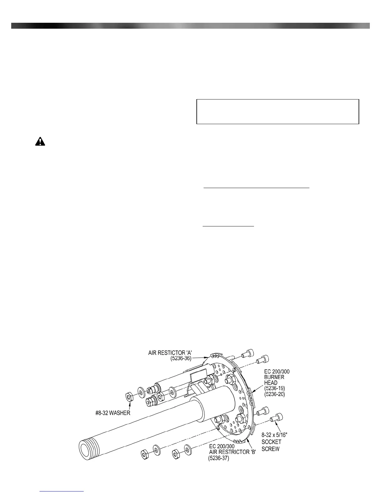
X - Air Restrictor
When the EC 200 burner is to be used at 150 MBH/hr and
below, or EC 300 burner is to be used at 200 MBH/hr and
below, the air restrictors should be installed on the burner head
to get the best combustion performance.
For easy installation follow the steps below.
1.Check the associated package containing two air
3600 x test dial size x BTU value
No. of seconds for one rev. test dial.
= BTU/Hr.
3600 x 1 x 1000
20
= 180,000 BTU/Hr. = 180 MBH
Example:
Midco International Inc. - Chicago IL - www.midcointernational.com
Figure 7: Air Restrictors
 Loading...