restrictors (A & B), four 8-32 x 5/16 socket screws and four
#8-32 nuts. NOTE: There is a slight difference between the
two air restrictors.
2.Disassemble the blast tube from the blower housing by
removing the nuts on the flange.
3.Put the air restrictor A in the place, see Figure 7 for
reference. The air restrictor A should be installed on the
back side of the burner head; on the same side of the
electrodes. Install one screw in the middle hole of air
restrictor and put one nut on the screw.
4.Put the air restrictor B in the place, see Figure 7 for
reference. Install one screw in the middle hole of air
restrictor and put one nut on the screw.
5. Line up two air restrictors and put the other two screws in
place. Then tighten four of them.
6.Assemble the blast tube back to the blower housing.
___________________________
XI - Nozzle and Electrodes
DANGER: Be sure that the Main Manual Shut-Off Valve,
Combination Valve and Burner Power Switch are turned off
before removing any parts for service.
Service will normally consist of inspection and cleaning.
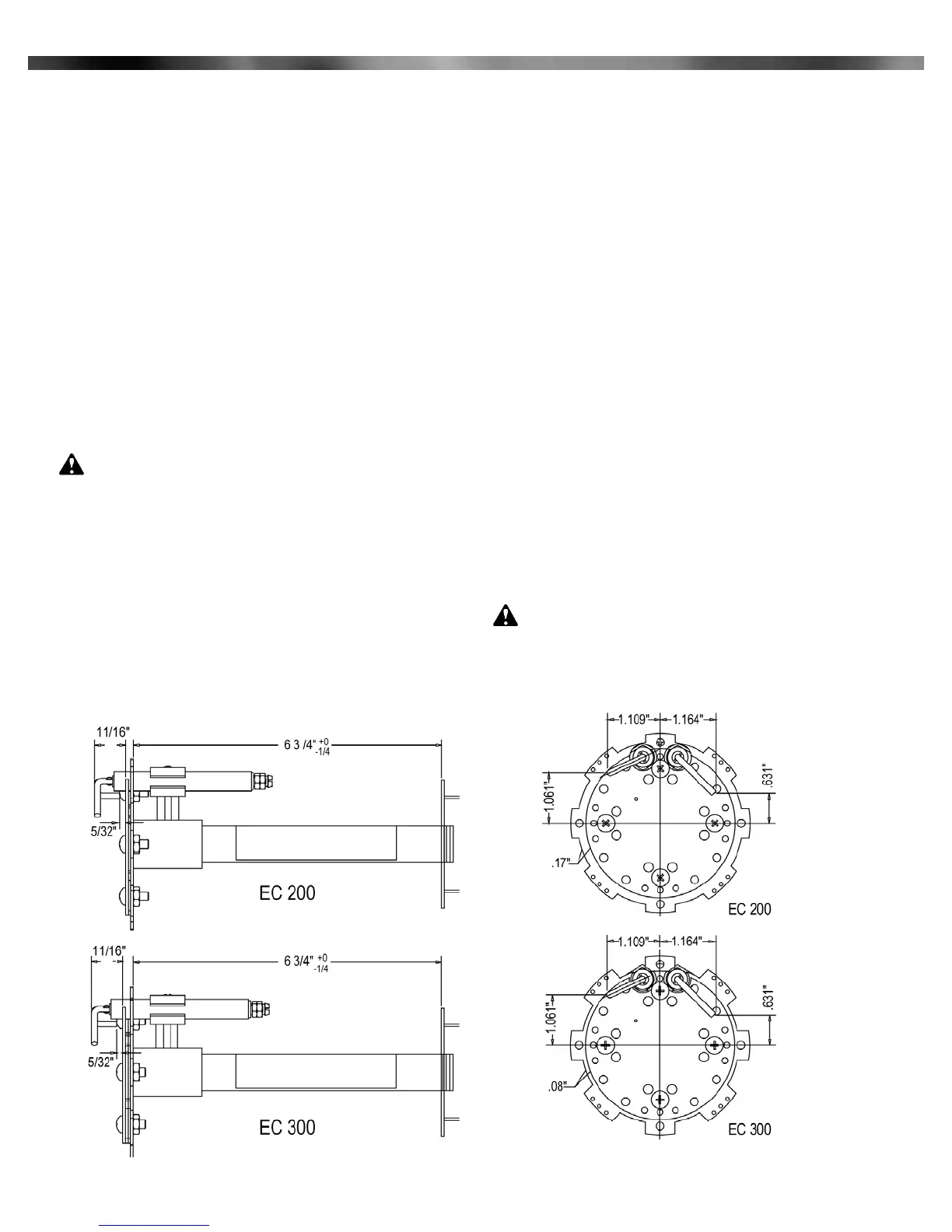
Check the electrodes for deterioration and the insulators for
cracks. The electrodes are adjustable. If defective replace. Be
sure to replace the rubber boot over the spark electrode and
treat electrode leads with care. Due to high voltage any damage
to the insulation is a potential leak path. When a new electrode
is installed, be sure to set the spark gap and flame sensor
dimensions, as shown in Figure 8.
___________________________
XII - Blower Assembly
Cleaning of the blower wheel is usually the only
service required. Need for cleaning is indicated if the air
inlet of the burner housing shows an accumulation of dust
and lint, or if the character of the flame—long, hazy and yel-
low (sooty)—indicates a deficiency of air. Motor air cooling
vents, if present, should also be cleaned at this time.
___________________________
XIII - Combination Gas Valve
The 24 volt Combination Gas Valve serves three functions:
1.Manual Gas Shut-off
2.Manifold gas pressure regulation
3.Automatic electric redundant (double seated) gas valve
For manual control the Manual Gas Cock Knob is
turned full ON or full OFF.
The Combination Valve Gas Regulator is factory set for
4.1" W.C. for the EC 200 and 4.0" for the EC 300. Manifold
Gas Pressure Tap is located on the outlet end of the
Combination Valve body.
If pressure adjustment is required to change settings,
remove regulator cap for access to slotted adjustment
screw. Turning of adjustment screw counterclockwise
reduces pressure; clockwise increases pressure. Do not
adjust past the point where no change in pressure is noted.
Note: Pressure setting can only be made with burner
running and gas on.
CAUTION: If the gas supply pressure is below its
specified range during adjustment, an overfire
condition could result when normal pressure returns,
particularly if the regulator adjustment screw is
bottomed out. ALWAYS confirm that at least the
8
Part 1 Installation
Figure 8: Retention Plates
Midco International Inc. - Chicago IL - www.midcointernational.com
 Loading...