FLEX-AUGER Installation & Operator’s Manual
•
Page 13
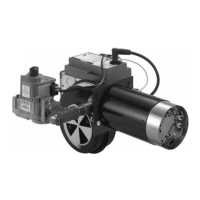
NOT ALLOWED. This system uses 180 degree elbows and would be
subject to premature elbow wear due to outlet drop placement before
an elbow. System C would be recommended.
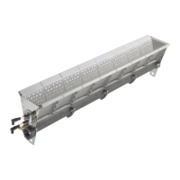
NOT ALLOWED. Too many elbows. The result would be auger vibration,
motor stall, and excessive elbow wear. A twin system, such as C, D, or
E, would be recommended; or an Extension Hopper could be utilized as
in System G.
Planning Chart for Model 55, 75, 90, & HMC Systems
"X" = distance from center of bin to where fill system enters the
building.
"H" = height from top of bin pad to where fill system enters the building.
Degree of elevation = Angle at which the system is installed, including
the 30 degree or straight-out Upper Boot.
These layout charts are for planning and reference purposes only. They
illustrate typical system layouts for the FLEX-AUGER Feed Delivery
Systems. Different combination of elbows and straight tube may be re-
quired for your installation, depending on the distance from the bin to
the building and the height at which the auger tubes are to enter the
building. PVC elbows are easily cut to any angle required.
PAY PARTICULAR ATTENTION TO THE MINIMUM DISTANCE FROM
BIN TO BUILDING.
Many installation and operational difficulties can be avoided if the bin
is located farther from the building. If in doubt, it is BETTER TO BE
TOO FAR AWAY THAN TOO CLOSE.
 Loading...