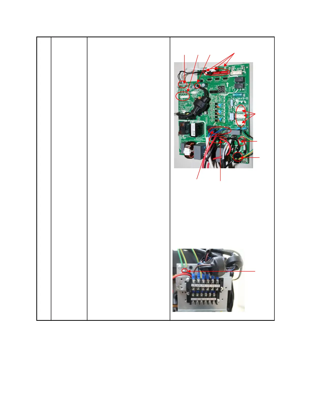
7) Disconnect the
connectors and wires
connected from PCB and other
parts.
Connectors:
CN17:T3/T4 temperature sensor
(2p/2p,white)
CN7: Discharge temperature sensor
(2p,white)
CN12:Ttop temperature
sensor(2p,white)
CN15:T2B-A,B,C temperature sensor
(2p/2p/2p,white)
CN18/CN19/CN22: Electronic
expansion valve A,B,C
(6p/6p/6p,red/red/red)
CN25/CN23/CN20: S-A,S-B,S-C
(3p/3p/3p,white/white/white)
Wires:
CN1/CN2: 4-way valve (blue-blue)
CN5/CN6: Crankcase heating cable
(red-red)
CN3:L1-IN (red)
CN4:L2-IN (black)
8) Disconnect the
grounding wire (yellow-green)
after removing the big handle
and the right-rear panel.
9) Remove the PCB board.