Installation & Owner's Manual
24
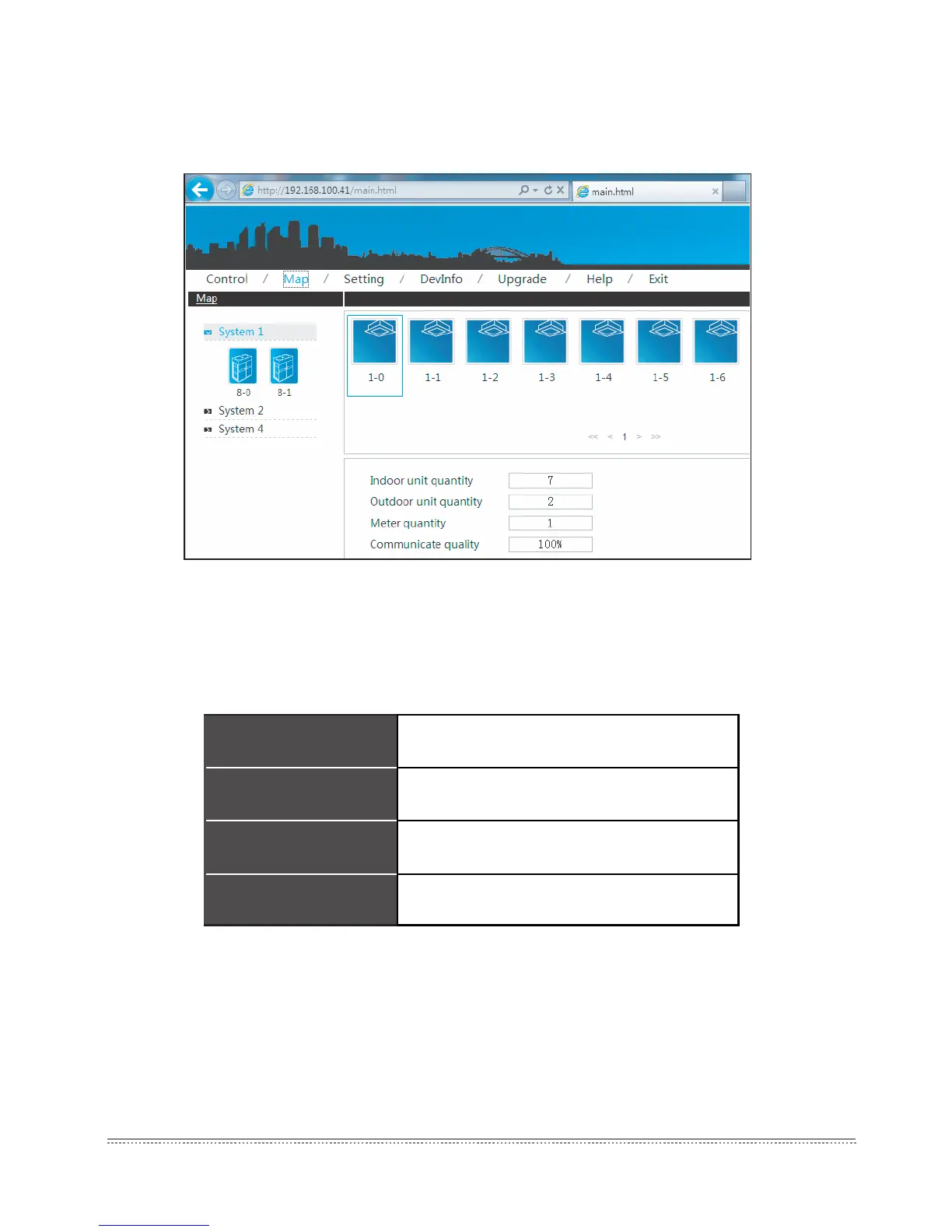
6.4 System mapping
Display the entire situation of refrigerant system, to reect the mapping relationship between the
indoor and outdoor units.
Fig.6-9
Select a single refrigerant system, the page display all the indoor unit pictures of this refrigerant
system, and the bottom of the page display the indoor unit quantity, outdoor unit quantity and ammeter
quantity. Click the single indoor unit to check the communication quality between this device and the
M-INTERFACE.
Characters instruction:
Table.6-2
6.5 Setting
For safety operation of M-INTERFACE, it only offer the “User management” function (Other
functions refer to the IMM TECHNOLOGY MANUAL).
6.5.1 User management
Offer the password changing function.
Indoor unit qty. of
refrigerant system
Calculate all the indoor unit qty. of
refrigerant system
Outdoor unit qty. of
refrigerant system
Calculate all the outdoor unit qty. of
refrigerant system
Outer ammeter qty. of
refrigerant system
Calculate all the ammeter qty. of refrigerant
system
Communication quality
Communication quality between single
device and M-INTERFACE gateway