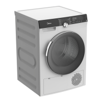
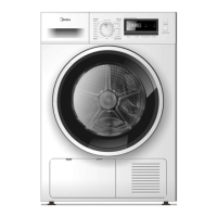
This document is a service manual for the Midea Tumble Heat Pump Dryer, model MDG80-CH05/B05E-EU(A2)-P2. It provides comprehensive information for servicing, troubleshooting, and maintaining the appliance.
Function Description:
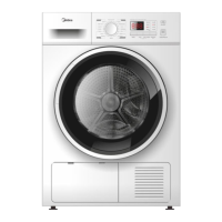
The Midea Tumble Heat Pump Dryer is designed to dry clothes using a heat pump system. This technology reuses hot air, making it more energy-efficient than conventional dryers. The dryer offers various drying programs, including options for different fabric types like Jeans, Bed Linen, Sports, Warm, Cool, Refresh, and specific settings like Standard, Iron, Delicate, Mix, and Extra. It features a control panel with an On/Off button, Start/Pause button, and indicators for Delay, Time, Anti-Crease, and Intensity settings, allowing users to customize their drying cycles.
Important Technical Specifications:
While detailed technical specifications like power consumption, dimensions, and capacity are not explicitly listed in the provided excerpts, the manual does offer insights into the internal components and their electrical characteristics, which are crucial for servicing. For instance, the "CHECK POINT OF CIRCUIT" section (page 32) lists parameters for various parts:
- Electric Filter: 250VAC 50/60HZ, 16A@40℃.
- NTC (Negative Temperature Coefficient thermistor): Multiple resistance values at different temperatures (e.g., 10℃ 9.6±5%KΩ, 15℃ 7.6±5%KΩ, 25℃ 4.8±5%KΩ, 30℃ 3.9±5%KΩ). These are critical for temperature sensing and control.
- Capacitor: Two types are mentioned, 7.5μF±10% 450VAC 50/60HZ and 16μF/450V, likely for motor operation.
- Drain Pump: 220-240V, 50Hz, 0.8M, 4L/min, 13W.
- Water Level Sensor: 10mV-24VAC; 10mV-200VDC, 10VA 10W, 10UA-1A(DC).
- Door Switch: 250V 16A.
- Motor Assembly: Primary and secondary windings with specific resistance values (e.g., Welling: Main winding(Green Orange) 26.5 × (1 ± 10%) Ω (20℃), Secondary winding(red-orange) 26.0 × (1 ± 10%) Ω (20℃); Sanjiang : Main winding(Green Orange) 23.1 × (1 ± 12%) Ω (20℃); Secondary winding(red-orange) 24.4 × (1 ± 12%) Ω (20℃)). This indicates a robust motor system.
- Compressor: S: START(Aux Winding), R: RUN(Main Winding), C: COMMON. Coil Resistance (at 20℃): Main: 11.37±5%Ω, Aux: 10.13±5%Ω. This confirms the use of a compressor, central to the heat pump technology.
The wiring connection figure (page 22) identifies key connection points (P0-P7) and their functions:
- P0: Neutral wire.
- P1: Live wire + Drain pump + Cooling fan.
- P2: Motor.
- P3: Humidity sensor.
- P4: Compressor.
- P5: Door switch + Lamp.
- P6: Communication between Displayed panel and Control panel.
- P7: Water level sensor +NTC1+NTC2.
Usage Features:
The manual primarily focuses on servicing, but some usage implications can be inferred. The presence of various drying programs suggests flexibility for different laundry needs. The "Factory Pattern Detection" section (page 9) describes a "Time" program for testing, where the dryer operates for at least 10 minutes, and the user checks for proper tumbling and absence of undesired noise. This indicates a basic operational check that a user might perform or that a technician would use to verify functionality. The control panel with Delay, Time, Anti-Crease, and Intensity options allows for user customization of drying cycles, enhancing convenience and fabric care.
Maintenance Features:
The service manual is a comprehensive guide for maintenance and repair. It emphasizes safety precautions throughout, including the use of genuine parts, proper grounding, observing warnings, performing safety checks after servicing, and insulation checks.
Disassembly and Unpacking:
Detailed instructions with pictures are provided for disassembling various parts of the dryer, which is crucial for maintenance and repair. This includes:
- Unfastening screws for the top cover board, front control panel, and top cover.
- Pulling out the water container and knob cover.
- Removing connection pins behind the control panel sub.
- Taking off the control box and central panel.
- Unfastening screws on the door hinge and inner ring, and removing the inner ring, door hinge, and door plunger.
- Removing the drain pipe and screws on the rear cover of the drain pump kit.
- Removing screws from the back cover and side plates.
- Unscrewing screws to remove the control board and pulling out all connection pins on the filter.
- Taking off the strainer and door sealing ring.
- Unscrewing screws for the door lock assembly, movable cover plate, and cooling fan cover plate.
- Moving the yellow clasp and taking off the maintenance cover.
- Unfastening screws on the front cover.
- Unscrewing screws on the side plates.
- Taking off two side plates and unfastening the belt.
- Fixing the motor shaft with a spanner and rotating the wind wheel anticlockwise.
- Unfastening the nut (M8) and screw of the capacitance and reinforcing plate, then removing the capacitance and reinforcing plate and pulling out all pins on the motor.
- Unfastening the screw of the bearing box.
- Pulling out the inlet and return pipes from all buckles.
- Lifting the tub assembly.
- Unscrewing screws on the bearing house assembly and removing the bearing cover.
- Unscrewing the nut(M8) and removing the bearing house assembly, separating the back cover from the tub.
- Unscrewing screws on the barrel and removing lifters.
- Unfastening screws on the front support, cooling fan, reinforce plate, and base.
- Pulling out all connections of the filter and control box, including connections for the tub lamp, cooling fan, humidity sensor, and door lock.
- Pulling out connections for the temperature sensor, compressor, motor, capacitance, water pump, and water-level detector.
- Removing screws on the front support, wire terminals of the lamp, felt ring seal, and humidity sensor support.
- Unfastening screws of the reinforcing plate and unscrewing the compression gasket.
- Removing the upper foam duct.
- Unfastening screws to remove the motor and motor bracket.
- Unfastening nuts (M6) and pulling out the pin of the temperature sensor and connection pin behind the cover.
- Removing the air conditioning unit from the bottom plate and the lower foam duct from the floor, and taking off the condenser baffle.
Troubleshooting:
The manual provides detailed troubleshooting flowcharts and error codes:
-
Error Codes (page 21):
- FUL (Flashing): Container is full; Water pump failure or water level sensor failure. The solution involves checking the water storage container, water pump, and water level sensor (consult section 5.6).
- E32: The fault of humidity sensor; Two parts of the sensor metal joint together. Solution: Warn when the cycle completed; Restorable. Check the humidity sensor and change control panel (consult section 5.7).
- E33: The fault of NTC. Solution: Termination of the program; Not restorable. Check the NTC connecting wire (consult section 5.8).
-
Troubleshooting Flowcharts (pages 23-28): These flowcharts guide technicians through diagnosing and resolving issues such as:
- The dryer breaking down and the control panel not displaying (checking fuse, power cord, filter, program controller, and plug insertion).
- The drum not spinning but the control panel displaying (checking belt, terminals of P3, door switch, wire assembly, tension spring, capacitance, front support wheel, motor, foreign body stuck in cylinder, and damage to the barrel axis).
- The heating system not working (checking use environment, program selection, filter, evaporator surface, motor operation, wind wheel, compressor, pipeline, condenser, refrigerant, compressor starter, cooling fan, pipeline temperature sensor, and compressor starter fault).
- Abnormal noise during operation (checking screw tightening, front support wheel subassembly, supporting wheel assembly, seal felt, screw, motor, wheel, barrel shaft, rolling bearing seat, drainage pipe, and overflow pipe).
- Abnormal smell during operation (checking belt slipping, motor stall, and other electrical components damage).
- "FUL" LED on permanently (checking container full of water, connection drainage pump and control board wire, drainage tube insertion, pump damage, drainage tube blockage, water level sensor, and tank dander accumulation).
- E32 after the cycle finished (checking humidity sensor and control panel).
- E33 lighting (checking terminals of P3, NTC, wire assembly, and control panel).
-
Heat Pump System Parts Repair (pages 29-31): Detailed steps for repairing specific components, including:
- Capillary and dry filter repair: Release refrigerant, melt capillary and dry filter, prepare new part, weld capillary/dry filter, vacuumize, fill refrigerant (R134a & 295g), seal, and face lifting and leak hunting.
- Condenser and evaporator repair: Similar steps to capillary repair, but specific to condenser and evaporator.
- Compressor repair: Similar steps to capillary repair, but specific to the compressor.
A list of essential service tools is provided (page 33), including:
- Sleeve (14#) or spanner for drum tub assembly.
- Sleeve (10#) and pliers for wheel assembly.
- Other common service tools like screwdriver and pliers.
- Vacuum pump, welding torch, butane and oxygen carrier, pipe cutter for welding and vacuuming.
This comprehensive manual ensures that technicians have all the necessary information to diagnose, repair, and maintain the Midea Tumble Heat Pump Dryer effectively and safely.