Do you have a question about the Midea MFM-24ARN1-Q and is the answer not in the manual?
To prevent injury and property damage, follow these instructions carefully.
Procedures for safe electrical work, handling sharp edges, and cable management during installation.
Reminders on refrigerant checks, water drainage, noise, lifting, and avoiding direct drafts.
Measurements (W, D, H) for the indoor unit, with accompanying diagrams.
Measurements (W, D, H, W1, A, B) for the outdoor unit, with accompanying diagrams.
Wiring details for the MFM-24ARN1-Q, covering indoor and outdoor units.
Wiring details for the MFM-48ARN1-R, covering indoor and outdoor units.
Wiring details for the MFM-60ARN1-R, covering indoor and outdoor units.
Guidelines for choosing suitable indoor and outdoor unit placement, considering space and environment.
Steps for anti-falling measures and removing the air-inlet grid before connecting pipes/wires.
Instructions for shipping, handling, and fixing the outdoor unit using bolts or a concrete base.
Specifications for refrigerant pipe length, elevation differences, and additional refrigerant calculation.
Procedures for connecting refrigerant pipes, including valve handling and leak checks.
Steps for initial system installation, including air purging and refrigerant charging.
Method for removing air from the system using a vacuum pump and checking for leaks.
Procedure for purging air using refrigerant from a charging cylinder.
Steps to add refrigerant when pipe length exceeds 5 meters, using liquid charge method.
Procedure for adding refrigerant to a system that has been in use for an extended period.
Steps to collect refrigerant into the outdoor unit when the indoor unit needs repair.
Procedure for purging air using refrigerant after re-installation.
Steps for evacuating the entire system when the outdoor unit requires repair.
Procedure for charging refrigerant into the system after outdoor unit repair.
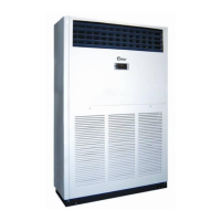
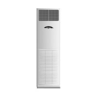
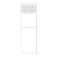
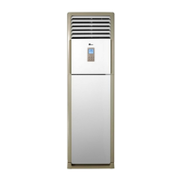
Labels for indoor unit parts like air outlet, panel, louvers, and inlets.
Labels for outdoor unit parts like drain pipe, cables, and air outlets.
Description of buttons on the control panel for mode, fan speed, and timer settings.
Explanation of various indicator lights signifying operational status and modes.
Introduction to main data points like Ts, T1, T2, T3, T4, T5 for system monitoring.
Details on compressor start-up delay, sensor protection, and phase sequence checks.
Rules for four-way valve, compressor, outdoor fan, and indoor fan during heating.
Rules for four-way valve, compressor, and outdoor fan during cooling mode.
Explanation of indoor fan speed selection (high, low, auto) and low evaporator temperature protection.
Explanation of T3 protection and its effect on compressor operation.
Descriptions of Dehumidifying, Auto, and Fan Only modes and their operational logic.
Information regarding LCD display content and the operation of timer functions.
Details on the economy mode for energy saving and refrigerant leakage detection function.
List and explanation of error codes (P4, P5, E1-E3, etc.) for indoor unit issues.
Correlation of LED states (On/Off/Flash) with outdoor unit faults.
Table listing common air conditioner issues and their probable causes and resolutions.
Diagnostic steps for open/short circuits in temperature sensors T1-T5.
Troubleshooting procedures for compressor phase issues and phase sequence errors.
Diagnostic flowcharts for high temperature and high pressure protection issues.
Diagnostic flowcharts for low temperature and low pressure protection issues.
Troubleshooting steps for current overload and communication malfunctions between units.
Detailed steps to diagnose and resolve communication errors between indoor and outdoor units.
Diagnostic steps for refrigerant leakage and related issues like air blowing and blocking.
Troubleshooting for compressor discharge temperature protection, including sensor and refrigerant checks.
A table mapping temperature (°C) to resistance (k Ohm) for sensors.
A table mapping temperature (°C) to resistance (k Ohm) for the discharge temperature sensor.
| Power Supply | 220-240V, 50Hz |
|---|---|
| Refrigerant | R410A |
| Type | Split System |
| Operating Temperature (Cooling) | 18°C to 43°C |
| Cooling Capacity | 24000 BTU/h |