Do you have a question about the Midea MSV1-09HRDN1-QC2A and is the answer not in the manual?
| Brand | Midea |
|---|---|
| Model | MSV1-09HRDN1-QC2A |
| Category | Air Conditioner |
| Language | English |
General safety instructions to prevent injury and property damage during operation and installation.
Important warnings and cautions for installation and operation to prevent hazards and ensure proper use.
Details on remote operation, sensors, fan control, and various indoor unit operational modes.
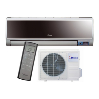
Overview of key features and functions of the outdoor unit components like fan and cabinet.
Physical dimensions and measurements for the indoor air conditioning unit.
Physical dimensions and measurements for the outdoor air conditioning unit.
Electrical wiring schematic detailing the connections within the indoor unit.
Electrical wiring schematic detailing the connections within the outdoor unit.
Torque values for tightening fittings during installation.
Instructions for properly connecting electrical cables to the unit.
Specifications for maximum refrigerant pipe length and elevation differences.
Procedure for removing air and moisture from the refrigerant piping.
Steps for recovering refrigerant during unit re-installation.
Procedure for re-purging air after refrigerant system re-installation.
Procedure to balance refrigerant levels between the 2-way and 3-way valves.
Procedure for creating a vacuum in the refrigerant circuit.
Procedure for adding refrigerant to the system.
Cooling and heating characteristics based on ambient temperature and piping length.
Cooling and heating characteristics based on ambient temperature and piping length.
Definitions of technical terms and abbreviations used in electronic functions.
Explanation of icons and indicators shown on the indoor unit's display.
Details on compressor protection, fan control, and error code explanations.
Description of how to operate the unit in fan-only mode.
Rules and features governing the cooling mode, including anti-freezing and current control.
Specific operational parameters for the drying mode.
Details on heating mode functions, fan control, and anti-cold-wind.
Conditions that trigger the unit to enter defrosting mode.
Sequence and timing of operations during the defrosting cycle.
Procedure to activate and use the rating capacity test function.
How the turbo function operates and affects performance in heating mode.
How the unit automatically selects cooling, heating, or fan-only modes.
Details on forced auto and forced cooling operation procedures.
Function of the 4-way valve in various operating modes.
Operation of the outdoor fan, including two-speed functionality.
Describes outdoor fan behavior in cooling, drying, and heating modes.
Settings and operation of the unit's timer functions.
How the sleep mode adjusts temperature and fan speed over time.
How the unit restores settings after a power interruption.
Functionality of the automatic opening and closing of the front panel.
How the ionizer feature cleans the air and its operational requirements.
Procedure for activating and operating the self-clean function.
Operation of the 'Follow Me' feature using the remote sensor.
Operation and control of the optional outdoor chassis heating cable.
Important safety warnings, especially regarding high voltage capacitors.
List of error codes displayed on the indoor unit and their meanings.
Step-by-step guides for diagnosing and resolving common unit errors.
Procedures for checking resistance of key electrical components.
Procedure for measuring the winding resistance of the compressor.
Procedures for measuring winding resistance of outdoor and indoor fan motors.
Procedure for measuring the winding resistance of the step motor.
Reference data for temperature sensor resistance values at various temperatures.