Air-cooled Package DM13-01.01.16en
50 Service manual
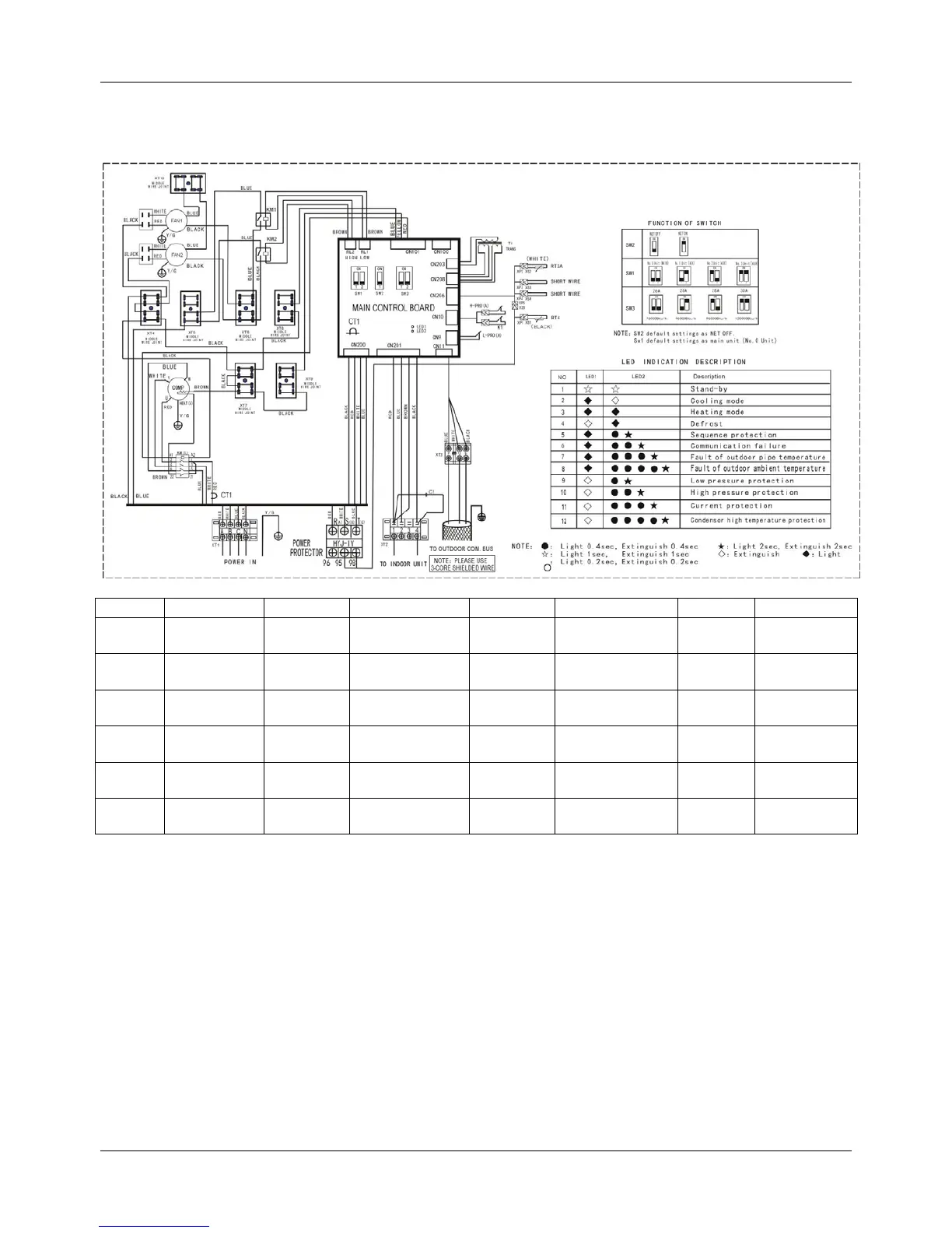
4. Wiring Diagrams
4.1 MOV-76CN1-C, MOV-96CN1-C, MOV-120CN1-C
Item Name Item Name Item Name Item Name
COMP Compressor HEAT(A) Crank RT3A
Pipe temp.
sensor
T1 Transformer
FAN1-2 Outdoor fan CT1
Current
detector
RT4
Room temp.
sensor
SW1-3 Switch
CAP1-2
Fan
capacitance
XT1-2 4-way terminal
XS1-5,
XP1-5
Connectors C1
Filter
capacitor
S.V 4-way valve XT3 3-way terminal L-PRO(A)
Low pressure
switch
KM1-2 Relay
KM(1)
AC
contactor
H-PRO(A)
High pressure
switch
K1
Temp. protect
switch
CN8-208
P.C. board
socket
XT4-10
Middle wire
joint
- - - - - -
 Loading...