R410A All DC Inverter V5 X Series 50Hz MCAC-VTSM-2015-10
156 Troubleshooting
If the value is not in the range, this indicates a problem with the electrolytic capacitor power supply, check the
power supply for high or unstable voltage.
If the voltage value is normal, then the main PCB has malfunctioned, it needs to be replaced.
4) L8/L9 troubleshooting
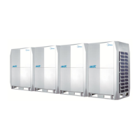
Step 1: Compressor check
Measure the resistance between each two of U, V, W terminals of the compressor, all the resistance should be
the same and equal to 0.9~5 Ohms. (Fig. A and Fig. B)
Measure the resistance between each U, V, W terminal of the compressor and ground (Fig. C), all the
resistance should be infinite (Fig. D), if not the compressor has malfunctioned and needs to be replaced.
If the resistance values are normal, then go to step 2.
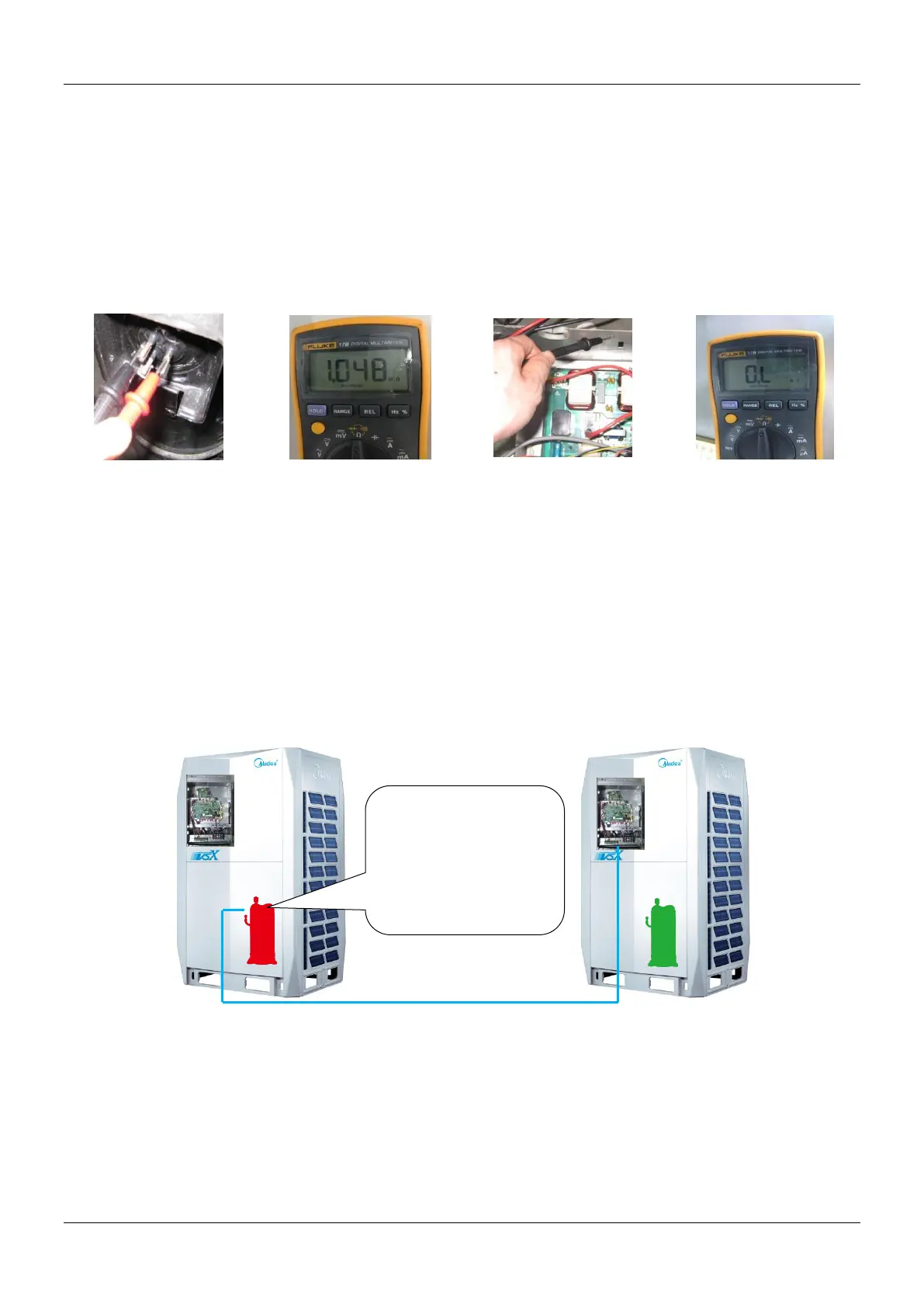
Step 2: Disconncet the power wiring from the compressor(named compressor A) of the faulted system(named
system A).
If there is a system running normally nearby (named system B):
Extend the power line of the inverter compressor of system B, connect compressor A to the control box of
system B, make sure that the U, V, W terminals are connected in right order, then start system B.
If compressor A can start normally, that means compressor is OK, the control box of system A has
malfunctioned, then replace the main PCB of system A and ensure correct wiring.
If compressor A can not start normally, that means compressor A is damaged and needs to be replaced.
If there is no normal system nearby:
Replace the main PCB of system A and ensure correct wiring, if compressor A can start normally, it means the
main PCB which was replaced was damaged. If compressor A still can’t start normally, replace the compressor.
Power line (U, V, W terminal)
Connect compressor A
to the control box of a
normal system B,
check whether
compressor A can start
normally
 Loading...