Flooded type water cooled screw chiller (PCB Control)
82
guided by design professionals, and confirm to the corresponding provisions of the HVAC installation
specifications.
Basically, the piping should be designed with a minimum number of bends and changes in elevation to
keep system cost down and performance up.
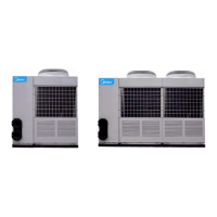
1) Condenser, cooling water piping suggested piping as follow:
Chiller
condenser
WS
a
c
d
e
g
h
j
i
k
Cond return water
Cond outlet water
Cooling
tower
(Condenser, cooling water hose connection diagrammatic sketch)
f Platinum resistance thermometer
Note: All of water pipe accessories and flow switch is provide by user.
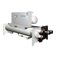
2) Chilled water piping suggested piping as follow:
Chiller
cooler
WS
c
d
e
g
h
j
i
k
b
Cooler return
water
Cooler outlet water
Return
water
Outlet
water
make-up waterexpansion
tank
(Chiller cooler piping diagrammatic sketch)
b Pressure type temperature controller
Note: All of water pipe accessories and flow switch is provide by user.
User must install flow switch in the outlet pipe of cooler and evaporator, it’s two sides must be level straight pipe
which length longer than five times of pipe diameter.
3) The water inlet pipeline and drain pipeline shall be connected according to the requirements of
markings on the unit. Generally, the refrigerant pipe side of the evaporator is the chilled water