Check all the joints with the leak detector or soap water. (See
Fig.9-6 as a reference illustration)
Be sure to with insulating materials cover all the exposed parts
of the flare pipe joints and refrigerant pipe on the liquid-side and
the gas-side. Ensure that there is no gap between them.
Incomplete insulation may cause water condensation.
9.2 Check The Leakage
9.3 Insulation
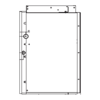
B A
D
C
Check-point of indoor unit
Check-point of outdoor unit
A. Lo-stop valve B. Hi-stop valve
C,D. Joints of the connecting pipe to the indoor unit.
Fig.9-2
9. REFRIGERANT PIPE CONNECTION
9.1 Expel The Air
Bend the pipe with thumb
Make the ends
straight
Fig.9-1
Fig.8-3
Fig.8-2
Locate The Pipe
Drill a hole in the wall (suitable just for the size of the wall conduit,
90mm in general), then set on the fittings such as the wall conduit
and its cover.
Bind the connecting pipe and the cables together tightly with
binding tapes. Do not let air in, which will cause water leakage
by condensation.
Pass the bound connecting pipe through the wall conduit from
outside. Be careful of the pipe all ocation to do no damage to the
tubing.
Connect the pipes.
Then, open the stem of stop valves of the outdoor unit to make
the refrigerant pipe connecting the indoor unit with the outdoor
unit fluently flow.
Be sure of no leakage by checking it with leak detector or soap
water.
Cover the joint of the connecting pipe to the indoor unit with the
sound proof/insulating sheath (fittings), and bind it well with the
tapes to prevent leakage.
●
●
●
●
●
Flaring
Cut a pipe with a pipe cutter.
Insert a flare nut into a pipe and flare the pipe.
90
lean crude burr
Then expose the pipe(cover it with tapes after bending).
To prevent collapsing of deforming, please bend the pipe at its
biggest radius.
Use bender to get a small radius pipes.
Use the market brass pipe.
Be sure to use the same insulating materials when you buy the
brass pipe. (More than 9mm thick)
●
Use frozen oil
Fig.8-1
●
●
14
installation manual
A
90+4
_
45+2
_
Outside diameter
A(mm)
Max
8.7 Φ6.4mm
Φ9.5mm
Φ12.7mm
Φ15.9mm
Φ19.1mm
12.4
15.8
19.0
23.3
8.3
12.0
15.4
18.6
22.9
Min
Table.9-1
Fig.9-3
Fig.9-4