Attaching wiring
The air conditioner should use separate power supply with rated
voltage.
The external power supply to the air conditioner should have
ground wiring, which is linked to the ground wiring of the indoor
and outdoor unit.
The wiring work should be done by qualified persons according
to circuit drawing.
A leakage protector should be installed according to the National
Standard concerning electrical appliance.
Be sure to locate the power wiring and the signal wring well to
avoid cross-disturbance and their contact with connecting pipe
or stop value body.
●
●
●
●
●
The wiring attached to this air conditioner is 10m long. Be sure
to prolong it with wiring of the same type and proper length
if necessary. Generally, do not twist two wiring together unless
the joint is soldered well and covered with insulator tape.
Do not turn on the power until you have checked carefully after
wiring.
●
●
11. WIRING
Capacity(KW)
200/250/280
16/10
2.5(<20 m)-4.0(<50 m)
2.0
0.75(<1200 m)
Circuit breaker/fuse (A)
Indoor unit power wiring (mm
2
)
Indoor/outdoor
connecting
wiring(mm
2
)
Ground wiring
Weak electric signal
Power
Phase
1-Phase
220-240V~50Hz / 208-230V~60HZ
Frequency and volt
Table.11-1
A disconnection device having an air gap contact separation in
all active conductors should be incorporated in the fixed wiring
according to the National Wiring Regulation.
CAUTION
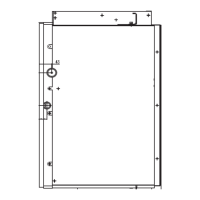
Fig.11-1
16
installation manual
Communication Wiring Chart
Communication wiring will be different according to the horse-
power of air-condictioners. The wiring of 71T1 to 160T1 indoor
unit, please refer to Fig.11-1, and Fig.11-2 is the communication
wiring for 200T1, 250T1 and 280T1 indoor unit.
The reserved function is indicated in broken line table,users can
select it when necessary.
CAUTION
NOTE
The air-conditioners can connect with Central Control
Monitor (CCM). Before operation, please wiring correctly
and set system address and network address of indoor
units.
TO CCM
COMM.BUS
Please use 3-core shielding wire, and ground the shielding layer.
TO INDOOR POWER SUPPLY
220-240V~ 50Hz / 208-230V~60Hz
L
N
YELLOW/GREEN
2
INDOOR UNIT
TO INDOOR&OUTDOOR
COMM.BUS
Fig.11-3
1
Terminal board diagram
Please refer to the indoor unit wiring diagram for the detailed
wiring. In accord with the communication wiring,
terminal board
wiring is different according to the horsepower of air-condictioners.
The wiring of 71T1 to 160T1 indoor unit, please refer to Fig.11-3,
and Fig.11-4 is the wiring for 200T1, 250T1 and 280T1 indoor unit.
10/10
INDOOR UNIT
XT2 XT3
(P、Q、E)
OUTDOOR UNIT
CENTRAL CONTROL
MONITOR (CCM)
(F
1
、F
2
、E)
COMPUTER
(X、Y、E)
INDOOR UNIT
XT2 XT3
INDOOR UNIT
XT2 XT3
(X、Y、E)
(P、Q、E) (P、Q、E)
INDOOR UNIT
XT2 XT3
......
Fig.11-2
71/80/90/112/140/160
INDOOR UNIT
(P、Q、E)
OUTDOOR UNIT
CENTRAL CONTROL
MONITOR (CCM)
(F
1
、F
2
、E)
COMPUTER
(X、Y、E)
INDOOR UNIT
XT2
INDOOR UNIT
XT2
(X、Y、E)
(P、Q、E)
INDOOR UNIT
XT2
......
XT2
The Specification of Power
Fig.10-2
Put as deep as possible
(about 10mm)
Downward declivity
lower than 1/100
VP30
Caution: While connecting the drain pipe, please use the drain pipe con-
nect to the secondary water holder simultaneously, for avoiding
there are little condensate water deposit in the unit when the machine
is running under the high humidity working condition.
(X、Y、E)
220-240V
~
50Hz