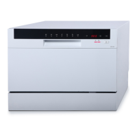
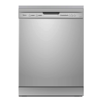
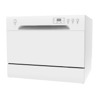
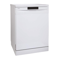
This document provides a technical service manual for a dishwasher, specifically focusing on the WQP8-9339L-US model. It covers the function description, important technical specifications, usage, and maintenance features of various components.
Function Description
The dishwasher's operation is controlled by a Printed Circuit Board (PCB), which acts as the central control unit. It receives and processes signals from components, sends commands, and handles feedback information. The water circuit involves several key components: the water inlet, inlet hose, inlet valve, upper and lower spray arms, sump, pressure switch, drain hose, overflow switch, drain pump, and washing pump.
The inlet valve is an electromagnetic valve that controls water entry. It is normally closed and opens upon receiving an electric signal from the controller when water is required. The inlet valve consists of an electric coil, valve body, valve pole, and filter.
The drain pump is responsible for expelling water from the dishwasher. It is a permanent magnet synchronous motor with a stator comprising a silicon steel stack and two coils (main and assistant). The rotor's inertia is very small, allowing for easy starting.
The heater is used to heat the water during the wash cycle. It includes two thermostats (Thermastat1 and Thermastat2) and a pressure switch for safety and control.
The washing pump, an asynchronous motor with a capacitor, circulates water through the spray arms for washing. Its stator has a silicon steel stack and two coils (main and assistant).
The pressure switch plays a crucial role in controlling the water level within the appliance. It consists of a moving diaphragm and disc that activate a change-over contact, calibrated to trip and reset at desired pressure levels. It may also provide flood protection.
The NTC (Negative Temperature Coefficient) Thermistor is integrated into the sump and measures the water temperature in the tub, providing feedback to the PCB for heating control.
The flowmeter, integrated into the air breaker, measures the amount of water entering the appliance. It comprises an impeller, tongue tube, and terminal. As water passes through, the magnetic impeller rotates, and the tongue tube senses the magnetic rotation, sending electronic pulses to the PCB.
Safety hoses are designed to prevent leaks. There are two types: mechanical Aquastop and electronic Aquastop. The mechanical type has two layers with foaming material between them; if water leaks into the air space, the material expands and locks the hose, triggering an E1 alarm. The electronic type also has two layers but features an electromagnetic valve that cuts off the water supply if a leak is detected on the bottom tray, triggering an E4 alarm.
Important Technical Specifications
General Specifications (WQP8-9339L-US):
- Electrical supply: 120-120V, 60Hz
- Supply water pressure: 0.04MPa-1.0MPa
- Supply water temperature: below 60°C
Inlet Valve:
- Nominal voltage: 110-120VAC
- Frequency: 60Hz
- Resistance: Approx. 1.0-2.2kΩ
- Work duty: 100%ED T25, 3min/5min T60
- Flux: 4L/min ±15%
- Power: 5W
- Work Pressure: 0.04-1MPa
Drain Pump:
- Nominal voltage: 110-120VAC
- Frequency: 60Hz
- Resistance: 78-110Ω
- Delivery height: 0.8M
- Delivery performance: ≥13l/min (230VAC)
Heater:
- Nominal voltage: 120VAC
- Rating power: 1000W
- Resistance: 14-20Ω
- Thermastat1: 98°C
- Thermastat2: 229°C
Washing Pump (9339L-US):
- Nominal voltage: 110-120VAC
- Frequency: 60Hz
- Main coil resistance: 23.8±7%Ω
- Assistant coil resistance: 34.6±7%Ω
- Delivery height: 1m
- Delivery performance: ≥46l/min
- Lock rotor current: ≤2.66A
- Operating current: 1.2A±10%
- Capacitor: 10μF
NTC Resistance Table:
- 15°C: 17.48KΩ
- 20°C: 12.12KΩ
- 25°C: 10KΩ
- 30°C: 8.299KΩ
- 40°C: 5.807KΩ
- 50°C: 4.144KΩ
- 60°C: 3.011KΩ
- 70°C: 2.224KΩ
- 80°C: 1.667KΩ
- 85°C: 1.451KΩ
Usage Features
The dishwasher is designed for ease of use, with a control panel that allows for program selection and operation. For basic operation instructions, users should refer to the instruction manual provided with each unit.
Test Program: A dedicated test program is available for technicians to check component operation and diagnose malfunctions. It can be activated by holding down the Start/Pause and Program buttons while pressing the Power button when the machine is off and the door is closed. The program pauses at step 00, and pressing Start/Pause again starts the test. During the test, Start/Pause can be used to jump to the next step (except for the inlet valve step).
Error Codes: The dishwasher provides error codes (E1, E2, E3, E4, E6, E7) to indicate specific malfunctions. These codes are displayed through combinations of flashing indicators (NORMAL, LIGHT, SPEED) and buzzer alarms.
- E1 (Water filling exceed pre-set time): Occurs if the inlet valve is open for 4 minutes but the desired water quantity (flow meter models) or pressure switch activation (pressure switch models) is not met. The drain pump activates, other components stop, and an alarm sounds.
- E2 (Draining exceed pre-set time): (For models controlling water filling by pressure switch 83/63 only) Occurs if the drain pump runs for 4 minutes but the water level pressure switch doesn't reset. The drain pump continues, other components stop, and an alarm sounds.
- E3 (Heating exceed pre-set time): Occurs if the heating element works for 60 minutes but the NTC-detected water temperature doesn't reach the desired value. The drain pump activates, other components stop, and an alarm sounds.
- E4 (Overflow): Occurs if the overflow micro-switch is active for more than 2 seconds. The drain pump activates, other components stop, and an alarm sounds. E4 has the highest priority.
- E6 (Open-circuit failure of thermistor): Detected by the controller during the test program. The drain pump activates, other components stop, and an alarm sounds.
- E7 (Short-circuit failure of thermistor): Detected by the controller during the test program. The drain pump activates, other components stop, and an alarm sounds.
Maintenance Features
Accessing Components:
- PCB: Located behind the control panel (majority of models) or on the side of the strengthening muscle (minority). Access involves removing screws from the control panel, disconnecting connectors, and then removing the PCB.
- Inlet Valve: Accessed by removing the baseboard, left baseboard, left side panel, and middle rear crosspiece. Terminals are disconnected, and the valve is pushed off.
- Drain Pump: Accessed by draining water, disconnecting power, removing bottom screws and bottom board, then disconnecting terminals and removing the pump.
- Heater: Accessed by draining water, disconnecting power, removing bottom board, disconnecting terminals and ground wire, and removing clamps from the heating element. Clamps are easily damaged and should be replaced.
- Washing Pump: Accessed by disconnecting power, removing bottom board, disconnecting terminals to the capacitor and motor wire connector, removing clamps from hoses, and disconnecting the ground wire.
- NTC: Accessed by removing the bottom board and two screws securing the NTC to the sump.
- Flowmeter: Integrated into the air breaker. Accessed by removing the baseboard, side baseboard, top panel, and side panel. The plastic nut securing the air breaker to the tub is removed, wires are disconnected, and the clamp fastening the hose is removed.
- Safety Hose: Accessed by removing the baseboard, side baseboard, top panel, and left side panel. Clamps are removed, bound belts are cut, and wire connectors are disconnected.
Inspection and Troubleshooting:
- Inlet Valve: Check electrical resistance (1.0KΩ to 2.4KΩ between blue (EV1) and white (IS) wires on CON3 and P4). If incorrect, check connections or replace the valve. Inspect the valve filter for blockages and the valve pole for rust or debris.
- Drain Pump: Check electrical resistance (78Ω to 110Ω between red (PS) and white (IS) wires on CON4 and P4). If incorrect, check connections or replace the pump. Inspect the non-return valve assembly and drain hose for blockages.
- Heater: Check electrical resistance (29Ω to 31Ω between terminals). If incorrect, replace the heating element or thermostat.
- Washing Pump: Check electrical resistance (23Ω to 36Ω between white (ML and IS) wires on CON4 and P4). If incorrect, check connections or replace the pump. If resistance is OK but it doesn't work, replace the capacitor. Inspect pump assembly for loose brackets, seal element for bonding, and vane wheel for blockages.
- NTC: Check resistance between blue wires on the RE connector. Refer to the NTC resistance table for expected values. If incorrect, check connections or replace the NTC.
- Flowmeter: Test for electrical pulses from two black wires on CON27 while water passes through. Continuous pulses indicate normal operation; no pulses indicate a circuit problem. Check connections or replace the air breaker.
- Electronic Aquastop Hose: Check electrical resistance between blue (EV1) and white (IS) wires on CON3 and P4. Open or short circuits are incorrect. Check connections or replace the safety hose.
- Mechanical Aquastop Hose: If it self-locks (can't fill water) due to moisture absorption by foaming material, it is non-resettable and requires replacement.
General Troubleshooting Advice:
- Always disconnect power before maintenance.
- Be careful of residual water when removing hoses.
- Label wires before disconnecting to ensure correct reassembly.
- If a problem persists after component inspection, the PCB may be malfunctioning and should be replaced.
- For E4 overflow, remove side panels, drain water from the bottom board, and run a strong wash program to check for leaks at higher temperatures. Observe the bottom tray for water and inspect components like the motor, drain pump, sump, softener, hoses, clips, and tub weld seams.
- Ensure proper detergent and rinse aid usage to prevent issues like excessive foam or poor washing performance.
- Regularly clean the filter to prevent blockages and E3 errors.
- Ensure the appliance is level to prevent E4 alarms.
- Check water pressure (0.04-1.0MPa) for proper water filling.
- Ensure drain hoses are not kinked or blocked.
- Proper loading of dishes and silverware is crucial for effective washing and drying.
- The inspection trees provided in the manual are for reference only, as real situations can be unpredictable.