and you will hear a “pop” or “tick” in the recording. This is a very bad thing, and clipping should be
avoided for the best quality recording! There is enough headroom so that you can be conservative in this
area, and there is no need to push the input levels (right delete word) up to the edge of clipping.
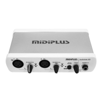
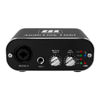
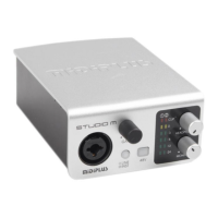
4. XLR MIC 2 Input: This XLR balanced connector accepts an instrument or line level signal for Channel 1
of the Audiolink3
5. MIC 2 level control: This level control regulates the level of the signal going from the Mic input. When
you plug a guitar or bass in the MIC / INST/Line input.
6. MIC 2 signal light: The Red one shows the input signal too high, and it will be cut the peak, while the
Green one shows the input signal is available. For optimal audio quality, you should adjust the input trim
knob so that your. loudest recorded signal lights up the yellow light, but not the red. When the red meter
light shines extra bright – you’ve clipped! If the signal level ever exceeds 0dBFS the signal will be
“clipped” and you will hear a “pop” or “tick” in the recording. This is a very bad thing, and clipping should
be avoided for the best quality recording! There is enough headroom so that you can be conservative in
this area, and there is no need to push the input levels right up to the edge of clipping.
7. USB Active light: This LED indicator lights signify USB communication state , USB communication
normal communication state led long bright, USB communication don't normally, kept flashing.
8. Direct Monitor: This is a direct monitor switch.
9. Headphone output level control: This level control regulates the level of the output signal form the
headphone amp.
10. Headphone Output Jack: This 1/4” stereo jack plays back outputs 1 and 2 through the Left and Right
speakers of your headphones.
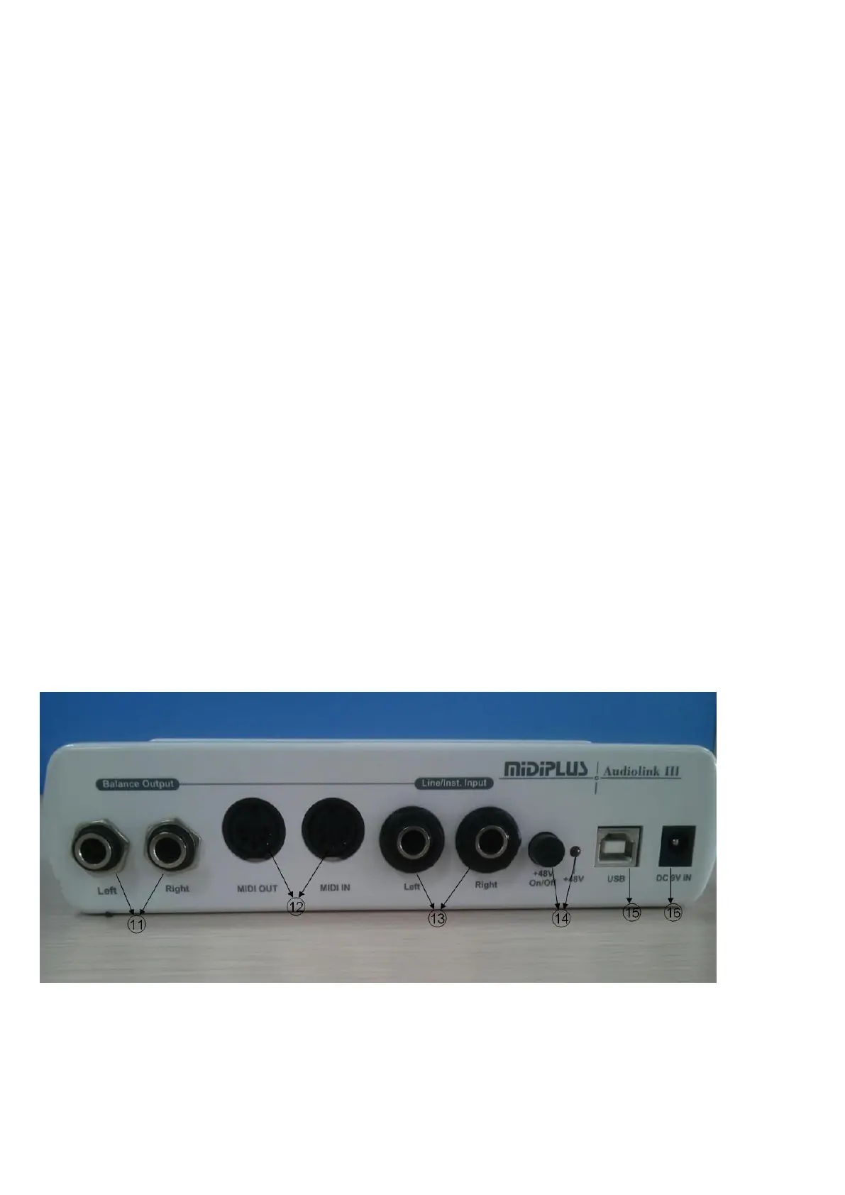
Rear Panel
11. Balance Output: These 1 /4-IN connectors are Balance outputs(Left & Right).