◆ Native USB 1.1 Port, on motherboard
◆ Windows@ 98SE, 2000 (SP2), ME, or XP (SP1 ) Home or Pro (128 MB )
◆ RAM required for XP Pro(128 MB)
◆ Recommended (1 GB)
◆ 700 MHz Pentium lll
◆ 128 MB RAM
◆ Windows 2000 (SP2 ) or XP (SP1 ) Home or pro
What’s in the box
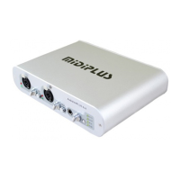
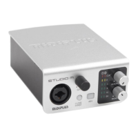
◆ Audiolink3 USB audio interface – 1 PCS
◆ User’s manual – 1 PCS
◆ USB cable – 1 PCS
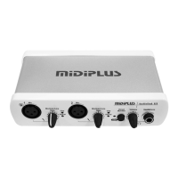
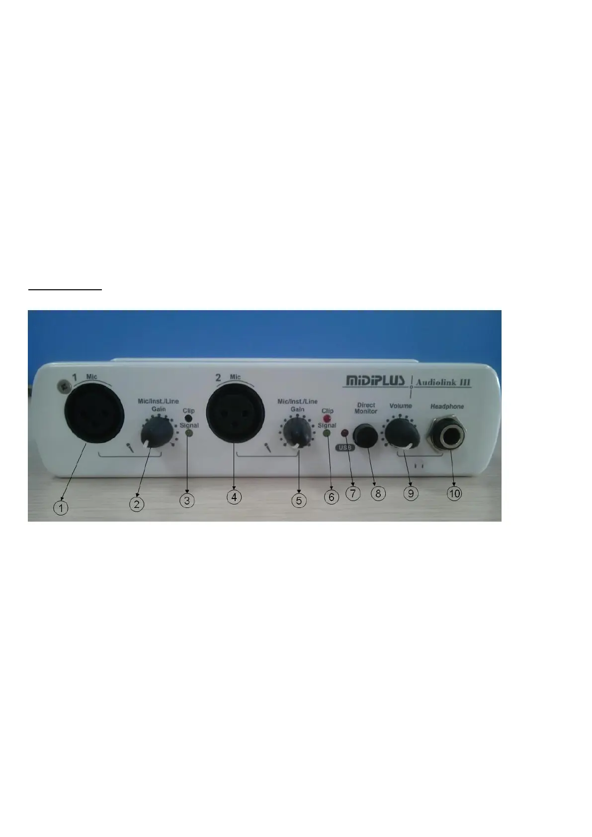
2. Description of the Audiolink3
Hardware Setup
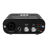
Front panel
1. XLR MIC 1 Input: This XLR balanced connector accepts an instrument or line level signal for Channel 1
of the Audiolink3
2. MIC 1 level control: This level control regulates the level of the signal going from the Mic input. When
you plug a guitar or bass in the MIC / INST/Line input. When a guitar or bass is plugged in to the
MIC/INST/Line input
.
3. MIC 1 signal light: The Red one shows the input signal too high, and it will be cut the peak, while the
Green one shows the input signal is available. For optimal audio quality, you should adjust the input trim
knob so that the loudest recorded signal lights up the yellow light, but not the red. When the red meter light
shines extra bright – you’ve clipped! If the signal level ever exceeds 0dBFS the signal will be “clipped”