9.2.10 After cleaning and confirming that the valve seat area is clean and free of defects, apply a small
amount of lubricant to the exposed thread of the valve stem.
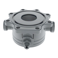
9.2.11 Install the new O-ring retainer (item 3) and secure it with the top locknut (item 7). Take care to
prevent rotation of the retainer using two wrenches. Refer to Table 1-2 for tools and torque
requirements.
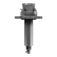
Figure 9-7 Reinstall Retainer and Locknut
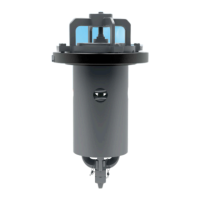
9.2.12 Install the top guide (item 1) and gasket (item 15), then secure with the four (4) top-guide bolts.
Refer to Table 1-2 for tools and torque requirements.
Figure 9-8 Reinstall Top Guide, Gasket and Bolts
CAUTION: Replace Retainer. After the tank-car pressure is relieved, replace the
retainer having epoxied O-rings with another one containing non-epoxied O-rings. If
valve leakage exceeds the sealing capability of the O-ring, replace or rebuild the
valve.
9.2.13 For special guidelines and precautions on pressure-testing and adjustment and for determining
applicable pressure values refer to AAR publication “Regulations for Tank Cars.” Appendix A
applies specifically to valves. This section prescribes the start-to-discharge pressure (STD), the
vapor-tight pressure (VTP) and their tolerances.
NOTICE: A “popping pressure” is not specified. It is only necessary to determine the
STD pressure as pressure is increased, and to determine the vapor-tight pressure
as pressure is being reduced. [STD is defined as a continuous discharge in contrast
to the start-to-leak pressure, which is defined as the first bubble leak. Vapor-tight is
defined as being bubble-tight, with no bubbles for two (2) minutes.]
 Loading...