Page 13 of 28
Manual content is subject to change.
Visit midlandmfg.com for latest IOM revision and revision history.
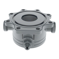
NOTICE: The ball valve should be installed in the “open” position so that
the ball surfaces are protected during the following steps.
F
igure 3-2 Ball Valve in Open
Position
Raise the valve up to the tank-car mounting flange surface. Orient with the valve handle shaft so that it is
pointing away from the tank car. Carefully align the mounting-flange tongue with the gasket groove in the valve.
Take care to align the mounting holes in the valve flange with those in the mounting flange.
CAUTION: Potential Lifting Injury. The ball valve, with the outlet cap in place, weighs in excess of 95 lb
(depending on model). Use mechanical assistance or additional manpower when lifting and locating the valve
during installation
Raise the valve only until the gasket groove engages with the mounting flange tongue.
Install four (4) mounting bolts 90° apart and tighten them gradually in an even sequence only enough to retain
engagement of the valve with the mounting-flange tongue.
Remove the mechanical lifitng device. Install the remaining four (4) mounting bolts.
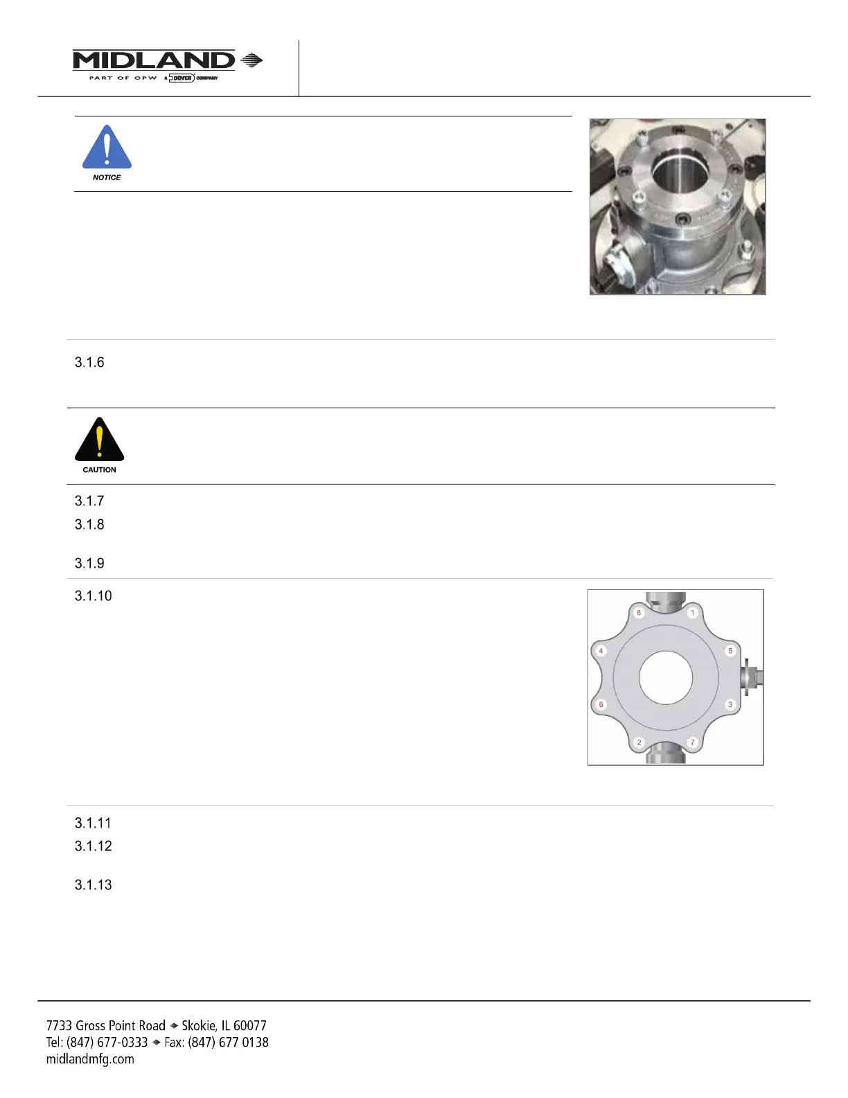
Tighten all eight (8) mounting bolts alternating diagonally. Do not over-
tighten one side as it may tilt the valve and prevent a proper seal.
Figure 3-3 Bolt-Tightening
Sequence
Tighten the mounting bolts in 1/3-torque increments to a final torque setting as determined by gasket selection.
Ensure that an even gap exists between the valve flange and the mounting flange. The gap should be 1/8” to
3/16” depending on the mounting flange tongue height (which may vary between 5/16” and 3/8”).
Fully close and open the valve a few times to confirm free operation.
A-520/A-522/A-522A, Rev. 3.0
 Loading...