Page 15 of 28
Manual content is subject to change.
Visit midlandmfg.com for latest IOM revision and revision history.
4 Valve Qualification
Follow these instructions and guidelines for assessing the condition of a leaking ball valve prior to rebuilding it.
NOTICE: To ensure best practices and consistency of your qualification procedure, gaskets, O-rings, valve
seats and wire seals should always be replaced.
Valve Disassembly and Required Tools
SAE Wrench Component(s)/Description
1-5/8” Wrench Locknut (item 13)
5/8” Allen Wrench Cap Screws (item 9)
Other Tools, Supplies, and Equipment:
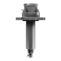
Thread Go/No-Go Gauge Stem (item 2)
Figure 4-1 Required Tools for Valve Disassembly
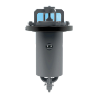
Set the valve to the closed position. This must be done to allow removal of
the valve ball.
F
igure 4-2 Set to Closed Position
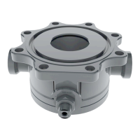
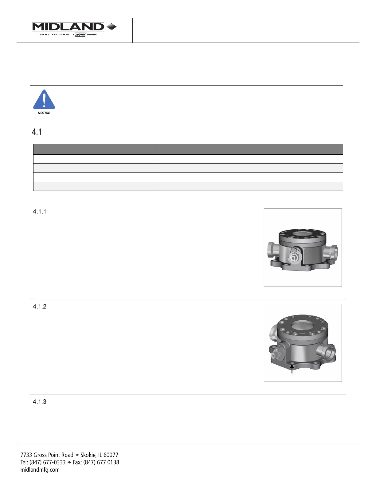
Locate the valve on a bench (preferably on a pressure-test fixture) so it may
be bolted for safety and rigidity during hardware removal. Secure it with the
eight-bolt flange.
F
igure 4-3 Valve Inverted
Remove the outlet cap assembly (if present).
A-520/A-522/A-522A, Rev. 3.0
 Loading...