Page 12 of 28
Manual content is subject to change.
Visit midlandmfg.com for latest IOM revision and revision history.
3 Valve Installation
Keep the new valve in its original shipping container. This will ensure it remains
clean and will protect the gasket groove and ball from nicks and damage.
Prior to installation, ensure that the valve remains clean and the gasket-sealing
surfaces are not damaged.
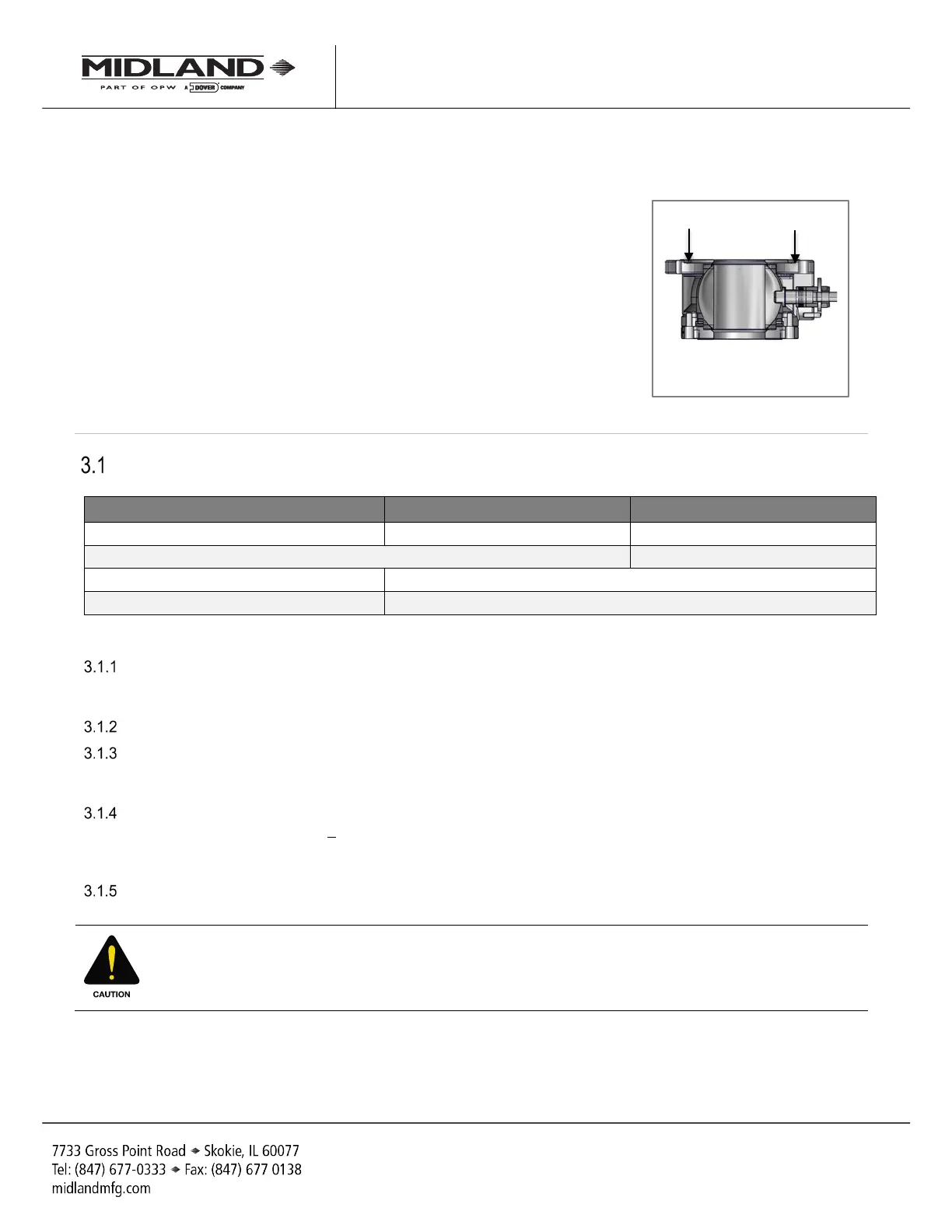
Figure 3-1 Gasket-Sealing Surfaces
Installation Procedure and Required Tools
SAE Wrench Component(s)/Description Torque
1-1/4” Mounting Bolts
Other Tools, Supplies, and Equipment:
Solvent To Clean the mounting and tongue
Lint-Free Cloth To Clean Sealing Surfaces
Table 3-1 Required Tools for Valve Installation
Remove the old valve from the tank car. Clean the tank-car mounting flange and saddle plate (if present) of all
product, debris and corrosion. Wipe the inside bottom of the tank near the outlet opening to remove loose
debris. Clean out the threaded holes in the mounting to ensure easy installation of the new mounting hardware.
Using a lint-free cloth and appropriate cleaning solvent, wipe clean the mounting and tongue.
Inspect the sides and edges of the tank-car tongue. Because the valve fits tightly over the tongue, any opening
over of its edges may make it difficult to properly seat the new valve. Mounted flange surfaces should be within
0.015 inches TIR. If any irregularities are found, correct them according to approved repair practices.
Inspect the gasket groove of valve for nicks and burrs. The mounting tongue and gasket groove dimensions
have diameter tolerances of +0.003 inches, thus any excess material on these diameters will make it difficult to
locate the valve groove on the tongue. If minor irregularities are found, correct them according to approved
repair practices.
Install the new gasket in the gasket groove of the valve. Ensure it is fully seated. When the gasket is fully
seated, 3/16" of free space should remain above the gasket to permit locating and entry of the tongue.
CAUTION: Gasket Damage. Do not use a sharp tool to press the new gasket into place or gasket damage
may result.
Gasket-Sealing Surfaces
A-520/A-522/A-522A, Rev. 3.0
 Loading...