Page 18 of 28
Manual content is subject to change.
Visit midlandmfg.com for latest IOM revision and revision history.
Component Inspection
NO
TICE:
Without consent from the valve manufacturer or car owner, repair work is limited to cleaning and
polishing. See AAR M1002, Paragraph A3.11.1 of the Tank-Car Specifications.
WARNING: Machining Not Allowed. Without consent from the valve manufacturer or car owner, machining,
grinding, welding or other alterations to the valve seat or stem seat is not allowed per AAR M1002, Paragraph
A3.11.1 of the Tank-Car Specifications.
NOTICE: Procedures may not cover all conditions encountered in the field. Therefore, it is the responsibility of
the repair agency to obtain approval from Midland for inspection, evaluation, repair and maintenance
procedures not covered herein. Evaluation of critical component metal surfaces of the valves after cleaning,
inspection, specialized testing performed by agencies other are the responsibility of the repair facility. Where
numerical tolerances can be provided, the disposition of the internal integrity and surface quality of parts is
under the jurisdiction of the repair facility and dependent on its experience and judgment.
Key components must be thoroughly inspected during the qualification process. These components include the valve-
body, valve-ball and valve stem.
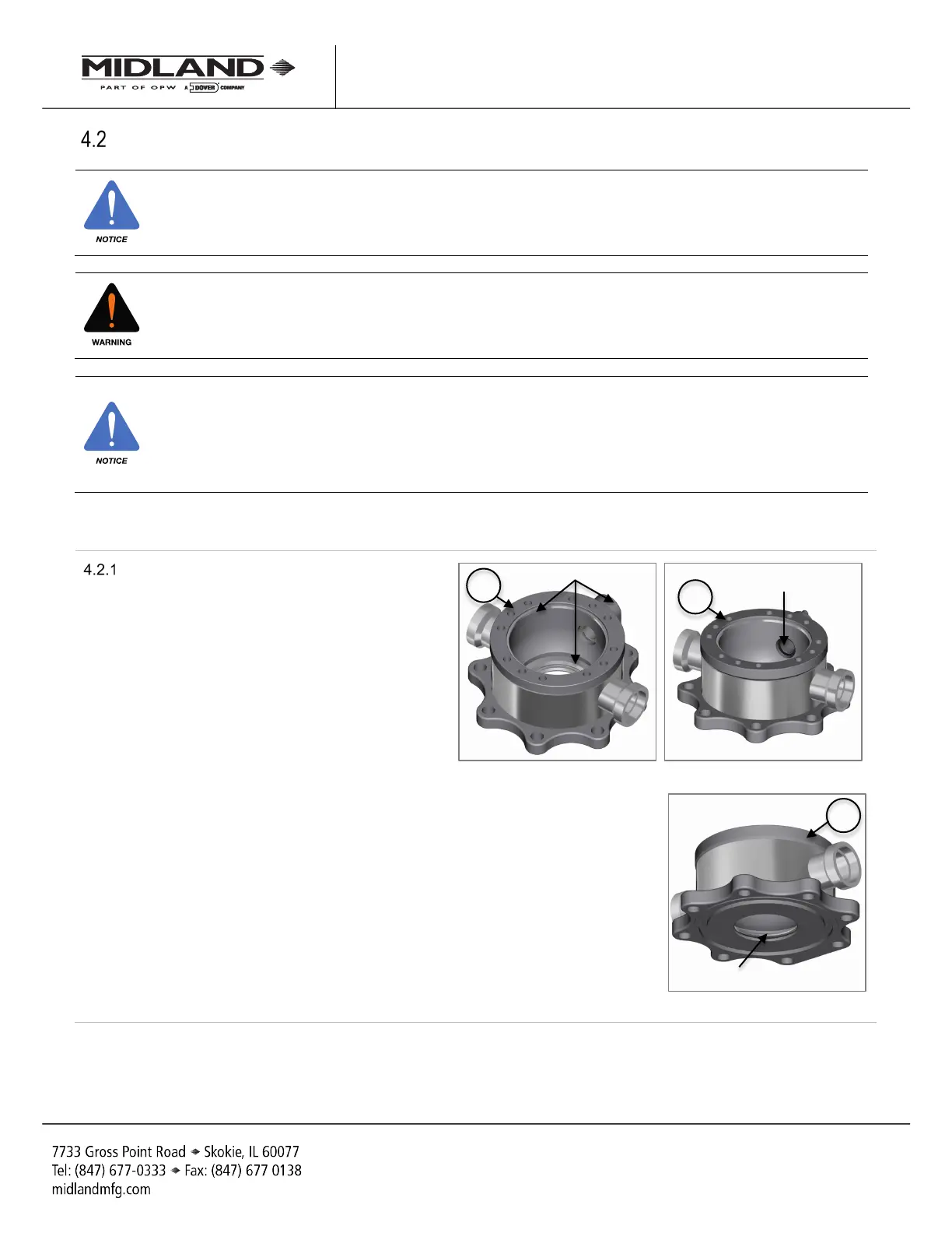
Valve-Body Inspection
4.2.1.1 Check the valve body (item 4), cap (item 1),
and the ball-
seal surfaces for signs of
corrosion, cracks and scratches. No
defects are allowed.
4.2.1.1 Inspect the sealing areas of the body (item
4)
. Ensure there is no visible corrosion,
intrusions or voids in the sealing area.
4.2.1.2 Outside the sealing area, the depth of the
voids/intrusions must not exceed 0.060” in
depth and 0.090” in width.
4.2.1.3 A maximum of one void per square inch is
allowable outside th
e sealing area. Total
void area must not exceed 5% of total
surface.
4.2.1.4 Bottom of voids must be visible, well-
rounded and without inclusions.
4.2.1.5 Using a light, visually inspect the valve stem
bore for gouges or corrosions. It must be
free of defects.
F
igure 4-12 Inspect Sealing Areas
Figure 4-13 Inspect Sealing Areas
Sealing areas
Sealing area
Sealing areas
A-520/A-522/A-522A, Rev. 3.0
 Loading...