Page 17 of 28
Manual content is subject to change.
Visit midlandmfg.com for latest IOM revision and revision history.
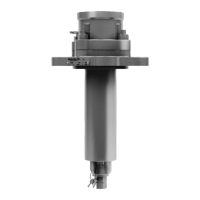
Remove the stop plate (item 8) and then
carefully press the valve stem (item 2) into
the body (item 4) cavity and remove it.
TIP: The use of a brass or plastic hammer
may be required to overcome the
resistance of the compressed stem
packing.
F
igure 4-8 Remove Stop Plate and Stem
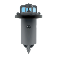
Remove the stainless-steel spacer collar (Item 6) from the valve-stem bore.
F
igure 4-9 Remove Space Collar
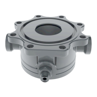
Remove the Teflon® packing (item 5) from the valve-
scratching or gouging the interior surfaces for the valve-stem bore.
F
igure 4-10 Remove Teflon Packing
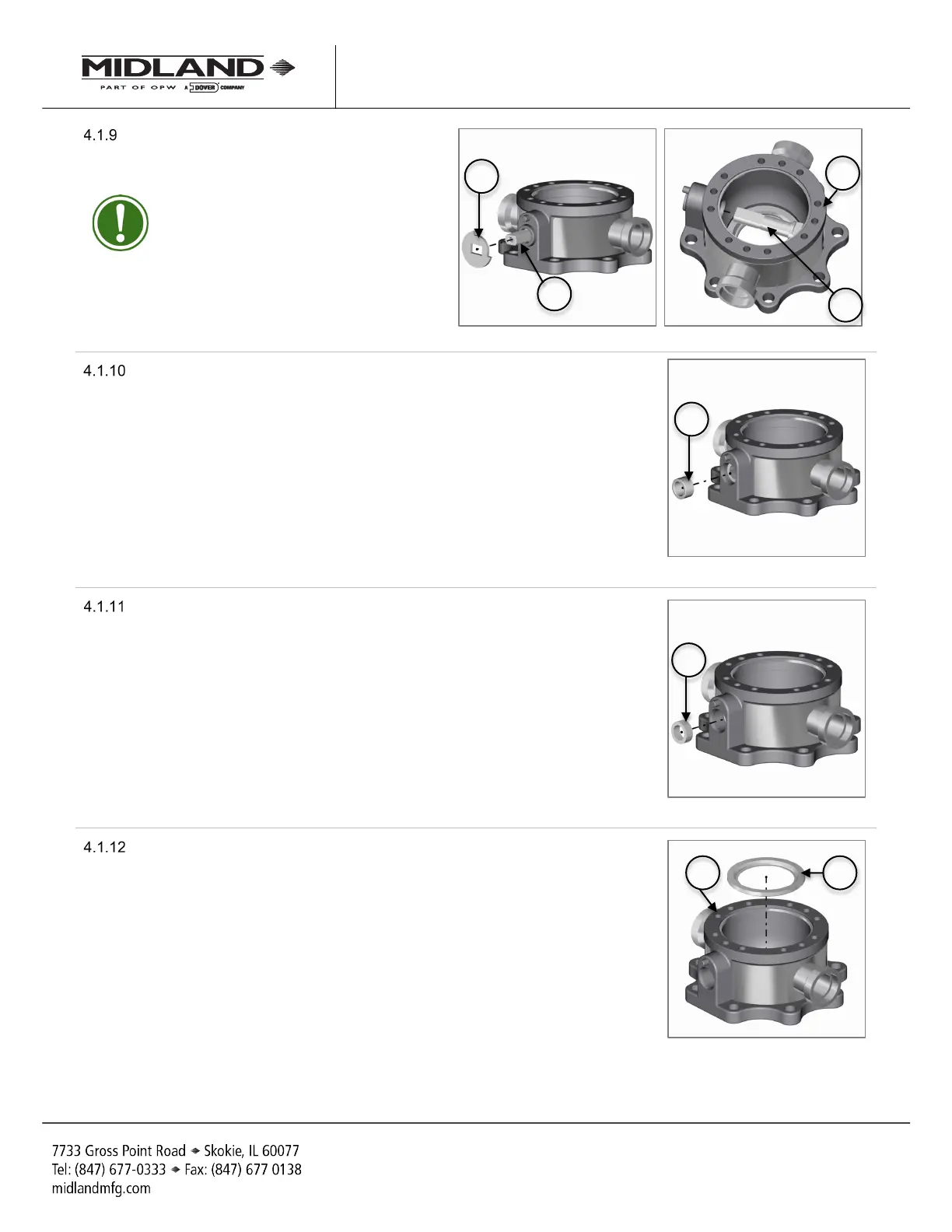
Carefully remove the body ball seal (item 10) from the inside-bottom of the
valve body (item 4).
F
igure 4-11 Remove Ball Seal
A-520/A-522/A-522A, Rev. 3.0
 Loading...