Page 16 of 28
Manual content is subject to change.
Visit midlandmfg.com for latest IOM revision and revision history.
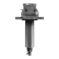
Remove the eight (8) socket hex-head cap screws (item 9) from the valve cap
(Item 1).
CAUTION: Valve Damage. Avoid using forceful tools on seal-support
surfaces when removing ball seals and stem packing, or damage may
result.
TIP: Use 5/8” Allen wrench.
F
igure 4-4 Remove Cap Screws
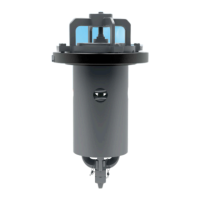
Carefully lift off the valve cap (item 1) taking
care to avoid contacting it with the valve ball
(item 3). Remove valve body seal (item 11)
from the body (item 4).
Remove the ball seal (Item 10) from the cap
(item 1).
4.1.6.1 If handling an A-522A, remove the cap ball
seal (item 15) from the cap (item 1).
F
igure 4-5 Remove Valve Cap and Ball Seal
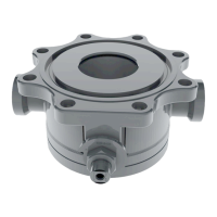
Reach both hands into the valve body (item 4) on either side of the valve ball
(item 3). Lift the ball out of the body and set it on a padded surface.
Figure 4-6 Remove Valve Ball
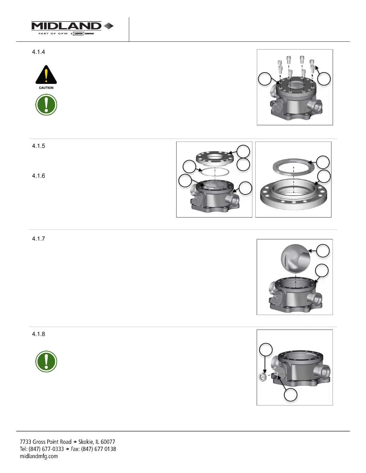
Remove the locknut (Item 13) from the valve stem (item 2) by turning it
counterclockwise.
TIP: Use a 1-5/8” wrench.
F
igure 4-7 Remove Locknut
A-520/A-522/A-522A, Rev. 3.0
 Loading...