Page 22 of 28
Manual content is subject to change.
Visit midlandmfg.com for latest IOM revision and revision history.
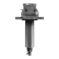
Install the stop plate (item 8). When oriented as shown, and with the valve
“Open” (as recommended to prevent ball-handling damage), the stop plate
part number etching will be visible and there should be an etched “O” nearest
the limiting pin. In this orientation, the stop plate assures that the valve will be
counterclockwise to “Close”
4.5.7.1 (Alt.) Stop plate installation for optional change of handle rotation to make it
clockwise to “Close”. Disregard Steps 4.5.7.1 through 4.5.7.3
specified.
Figure 4-20 Install Stop Plate
CAUTION: The following instruction is critical to be completed as described here. Failure to follow this
specifically could result in an incorrect orientation of the ball and its vent hole that would negatively impact
orientation.
(Alt) Using an assembly tool that is compatible with the threaded end of the stem or temporary handle installation, turn
the stem to put the valve in the “Closed” position.
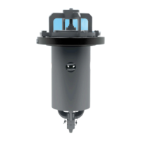
4.5.7.2 (Alt) Install the stop plate (item 8) as shown, except flip the stop plate so
that the part number etching is on the opposite side and not visible.
In addition, the stop plate must be oriented so that the etched “C” is nearest
the position-limiting pin. (It will be necessary to view the opposing side of
the stop plate to ensure this is correct.)
4.5.7.3 (Alt.) Using an assembly tool compatible with the threaded end of the stem
or temporary handle installation, turn the stem to put the valve in the “Open”
position.
Figure 4-21 Stop Plate Etching
Identification
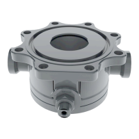
Install the locknut (item 13) and torque it to 150 ft-lb.
The gap between the stop plate (item 8) and the valve body (item 4) must be
1/8” minimum and 1/4” maximum.
Figure 4-22 Gap Between Stop
Plate and Valve Body
A-520/A-522/A-522A, Rev. 3.0
 Loading...