Page 26 of 28
Manual content is subject to change.
Visit midlandmfg.com for latest IOM revision and revision history.
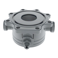
Place the vavle in a suitable test fixture and pour water into the valve outlet
port so that it covers the sealing area.
F
igure 4-34 Immerse Seal for Leak
Test
Apply air pressure to the valve at 300 psig.
Brush away initial bubbles and look for any new ones during a two-minute dwell period. No new bubbles are
allowed. If any new bubbles appear during test period, the valve must be rejected.
Siphon or wipe the water from the valve port. Blow it dry with an air gun.
Depressurize the valve body (item 4).
Manually adjust the valve so that it is half open.
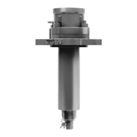
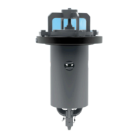
Pressurize the assembly with air to 300 psig for two (2) minutes using a blind
flange or outlet leg closure. During this period, apply leak-
(snoop) to the exterior of the spacer protruding from the shaft bore while
watching for any bubbles and foaming. No leaks are allowed.
After first inspection use a fine brush to pop the bubbles that were created
from the first test.
Using the vent valve, lower the pressure to 50 psig for two (2) more minutes.
During this second period, re-apply leak-detecting fluid (Snoop or commercial
synthetic bubble-
leak solution equivalent) to the exterior of the spacer
protrudinf from the shaft bore while watching for any bubbles and foaming.
No leaks are allowed.
F
igure 4-35 Valve Stem Leak Test
Depressurize the valve body (item 4) and remove the sealing cap. Wipe off any remaining water.
Fully open the valve and install a protective cap in the outlet port.
Remove the four (4) 5/8”-11 UNC 2A 1-3/4” long cap screws (item 9) from the valve cap (item 1).
Remove the valve from the assembly/test fixture.
A-520/A-522/A-522A, Rev. 3.0
 Loading...