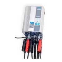
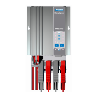
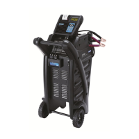
ChargeXpress PRO 50-2 ChargeXpress PRO 50-2
Midtronics bv. Hoofdveste 6 - 8 Houten NL
www.midtronics.com
Midtronics bv. Hoofdveste 6 - 8 Houten NL
www.midtronics.com
10
11
Chapter 3: Geng Started
Chapter 3: Geng Started
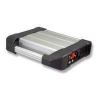
Before connecting the unit to the mains please connect the
charge cables to the unit. Charge cable #1 goes into position
4, charge cable #2 goes into position 5. Make sure the charge
cables are connected nice and tidy under the strain relieve
shown in position 8 using the bracket with the wing nut.
Plug in the AC power cable at position 1.
1. AC power cable
2. ON / OFF switch
3. Volt sensing connector 1
4. Charge cable 1
5. Charge cable 2
6. Volt sensing connector 2
7. Programming connector
8. Strain relief
Fitting Installations
The charger can be mounted vertically or horizontally, while
maintaining a free area of 15 cm (6’’) all around. This allows
an optimal cooling with air circulation.
Visual Inspection
Visually inspect the battery before charging. If there are any
signs of a leaking or cracked case, discard the battery. Do not
attempt to charge a battery that is in this condition.
PLEASE BE AWARE THAT THIS PLUG IS FOR PROGRAMMING
ONLY. PLUGGING ANY OTHER CABLE MAY CAUSE DAMAGE
TO THE CHARGEXPRESS PRO.
1
2
3 54 6
7
8
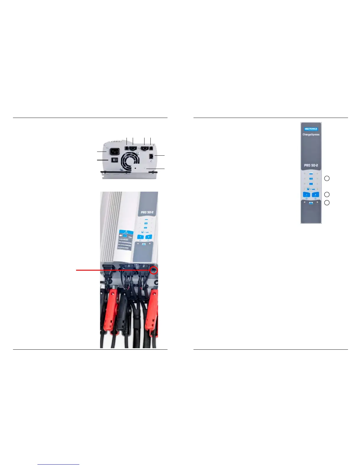
Chapter 3: Getting Started
Front Panel
1. Function selection LED’s
2. Multi Function and POWER buttons
3. Status LED’s
1. Function LED
Each charger channel has 4 LEDS to indicate the selected
function. A blinking LED indicates a fault, see therefore the
code table.
2. Multi Function and POWER buttons
Charger is OFF
Holding the POWER button for four seconds turns the power
on. A self test is performed by the charger, if everything is OK
both status LEDS will turn to green. If LEDS don’t turn green,
check the error code under the Trouble codes section in this
manual.
With the charger switched ON press the Multi function
buttons consequently to scroll through the available battery
technologies. When the button is no longer pressed, the
charger automatically accepts this selection.
Charger is now ready to charge a battery.
Charger is ON
Pressing the Multi Function POWER button quickly
(less than 1 second) stops the battery charger, if active.
When Multi Function and POWER button is pressed for more
then 2 seconds the charger switches completely o.
3. Status LED’s
Located at the bottom of the charger are two multi coloured
LEDS. Each charger channel has one LED assigned. When the
charger is switched on a self-test is performed. If something
is not according to specication the multi coloured LED will
turn RED.
Possible colours:
Green
• Indicates charger is OK, when the charger is not actively
charging a battery
• Continuous; fully charged battery
Red
• Solid Red LED. Charger internals are not OK.
• Blinking RED LED Blink rate indicates a fault. Count the
blink rate and check trouble- shooting section for more
details.
Orange:
• Solid lit LED indicates that battery is being charged.
1
2
3