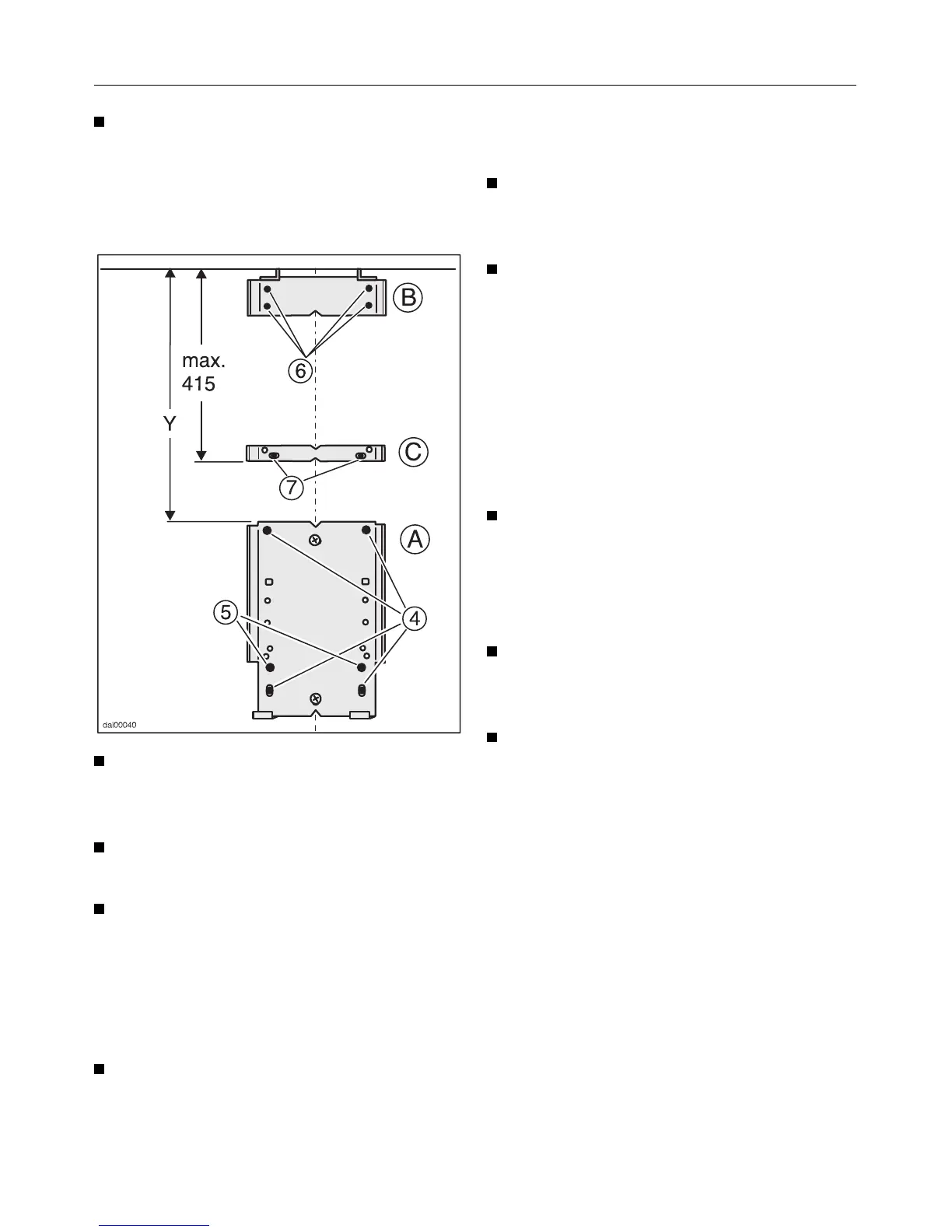
Lightly screw on the retaining plate A
with 5 x 40mm screws through the
two holes
b and use the notches to
align on the middle line.
Drill 4 more holes e 8 mm Ø through
the now mounted retaining plate and
press S8 plugs into the holes.
Screw in 4 screws 5 x 40 mm into
the plugs.
Drill 2 holes f 8 mm Ø to be used
later to secure the vapour guide / ca-
nopy and press S8 plugs into the
drilled holes.
Retaining Plate B
Hold the retaining plate B to the wall
and push up until it is directly below
the ceiling. Use the notches to
centre horizontally to the middle line.
Mark the 4 drill holes
g on the wall.
With a 6 mm Ø bit drill the 4 holes in
the wall and then press the S6 plugs
in the holes.
Screw in the top retaining plate with
4 screws 4 x 30 mm and 4 under-
lying washers, 4.3 mm.
Retaining Plate C
Retaining plate C must now be fitted if
dimension Y is greater than 415 mm.
The plate gives greater stability to the
extension piece.
At a maximum distance of 415 mm
from the ceiling hold retaining plate
C to the wall and use the notches to
centre on the middle line. Mark the
two drill holes
h.
With a 6 mm Ø bit drill the 2 holes in
the wall and press the S6 plugs into
the holes.
Secure plate C with 2 screws,
4 x 30 mm and 2 underlying
washers, 4.3 mm.
Installation
20