Technical Information
72
G 600/G 800
3. Lift the fascia and control panel from the appliance.
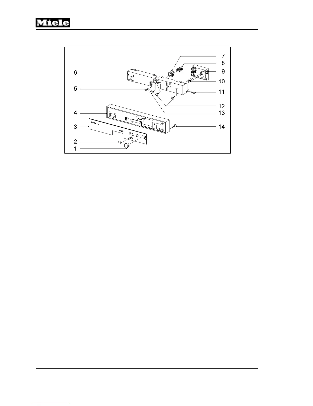
Figure 5-39: Control Panel (Novotronic and Touchtronic)
1 Program selector switch 8 Pushbutton switch cap
2 Start button 9 Electronic
3 Control panel 10 Program selector switch adapter
4 Fascia panel 11 Screw
5 Door closure screw 12 Screws
6 Mounting bracket 13 On/off switch cap
7 Pushbutton switch adapter 14 Screw
5.48 Mounting Bracket Removal
The mounting bracket is removed to access the following components:
Turbothermic fan/PTC release
On/off button
Door handle/lock assembly
Electronic(s)
1. Remove the control panel. See Section 5.46 or 5.47.
2. Remove one screw from each side of the door (Figure 5-40, Item A).
3. Support the mounting bracket; remove the top screw (Figure 5-40, Item B)
4. Carefully lower the mounting bracket away from the door.
 Loading...