Philips Semiconductors Rev. 1.0 November 2002
13.56 MHz RFID Proximity Antennas mifare
®
(14443A)
5 PUBLIC
3 THE MIFARE
®
RF INTERFACE
The MIFARE
®
technology describes an ISO 14443-Type A compliant RF interface for a communication
between a PCD and a PICC.
Table 1 gives a short overview on the MIFARE
®
RF interface. Essentially the MIFARE
®
RF interface follows
the transformer principle, although both the PCD and PICC antenna of course are resonance circuitries as
antennas usually are. The PICC is passive with no onboard battery. Thus, an energy transmission from the
PCD to the PICC is required in addition to the communication (data transmission) in both directions between
the PCD and the PICC (see Figure 1).
Table 1: Overview MIFARE
®
RF interface
Energy transmission
Transformer principle; MIFARE
®
card is passive
Operating frequency
13.56 MHz
Communication structure
Half duplex, reader talks first
Data rate
105.9 kHz
Data transmission
RWD Æ Card
Card Æ RWD
100 % ASK, Modified Miller Code
Load Modulation, Subcarrier 847.5 kHz,
OOK, Manchester Code
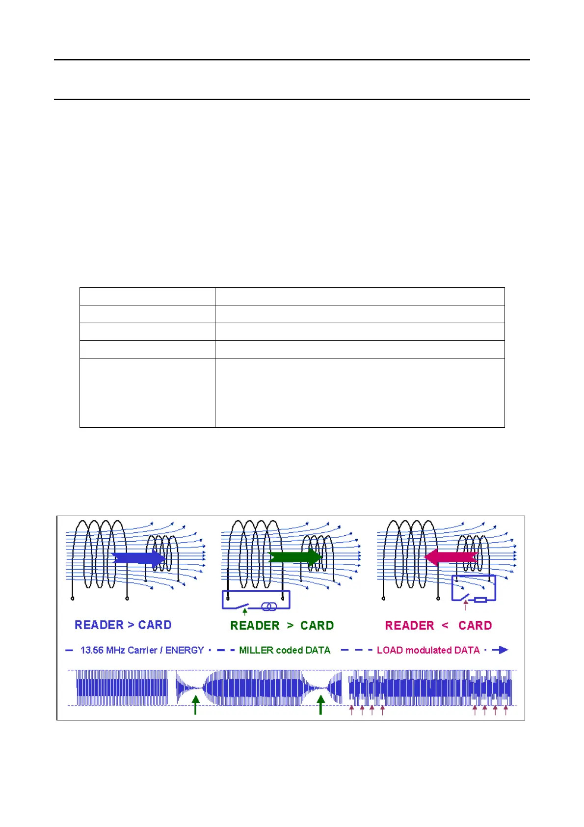
In the following the fundamentals of the MIFARE
®
RF interface are described starting with the basic energy
transmission. Finally, the data transmission and the used data coding in both directions will be shown.
Figure 1: Mifare Interface Principle
 Loading...