Philips Semiconductors Rev. 1.0 November 2002
13.56 MHz RFID Proximity Antennas mifare
®
(14443A)
6 PUBLIC
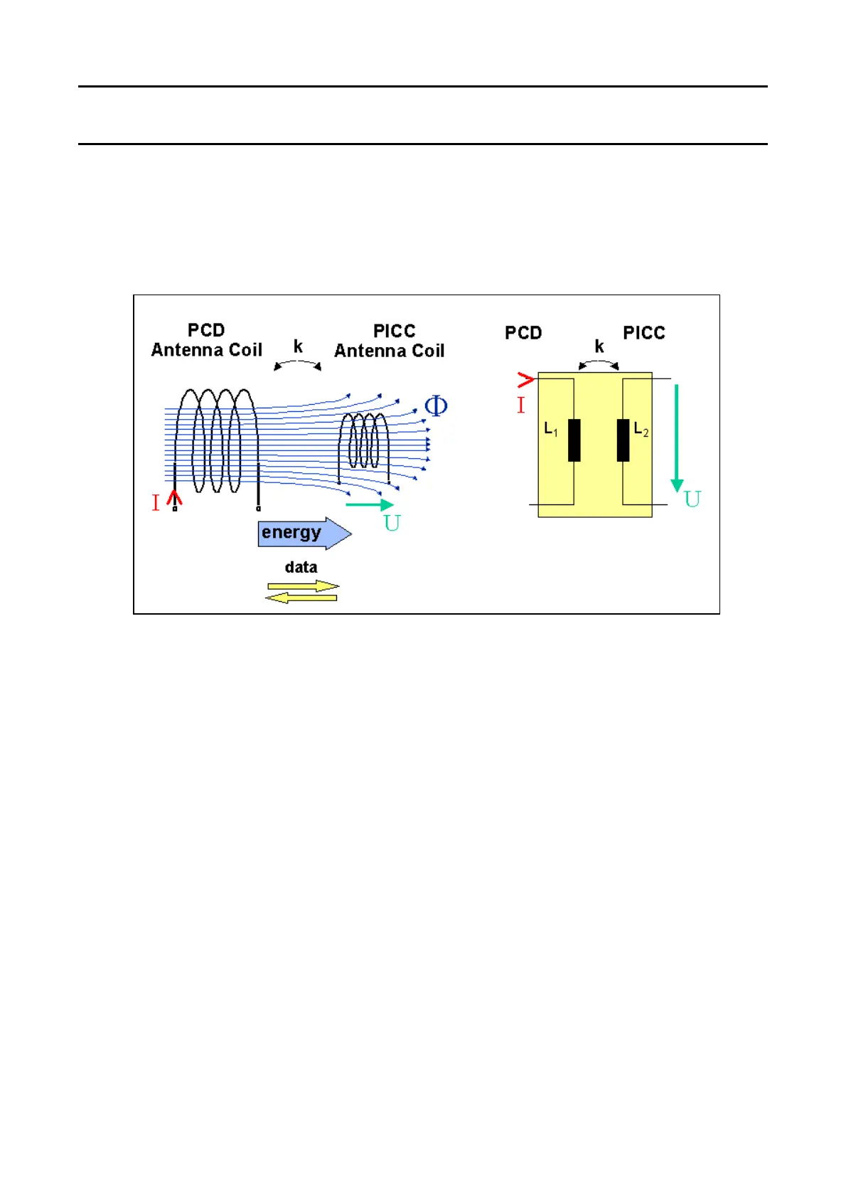
3.1 Energy Transmission
The energy transmission from the PCD to the passive PICC is based on the transformer principle. At PCD
side an antenna coil is required as well as a card coil implemented in the MIFARE
®
card (PICC). Figure 2
shows the basic principle and the equivalent electronic circuitry.
Figure 2: Transformer Model
The figure’s left part describes the antennas and the energy transmission. The current I in the PCD antenna
coil generates a magnetic flux Φ. Parts of this flux Φ flow through the card coil and induce a voltage U in the
card coil itself. This voltage U is rectified and the card IC is activated when the operating voltage is reached.
The induced voltage will vary within the distance between PCD antenna and the PICC. Due to that voltage
variation, the achievable operating distance is limited by the transferred power.
The right part shows the equivalent electrical circuitry, the transformer model.
 Loading...