Philips Semiconductors Rev. 1.0 November 2002
13.56 MHz RFID Proximity Antennas mifare
®
(14443A)
9 PUBLIC
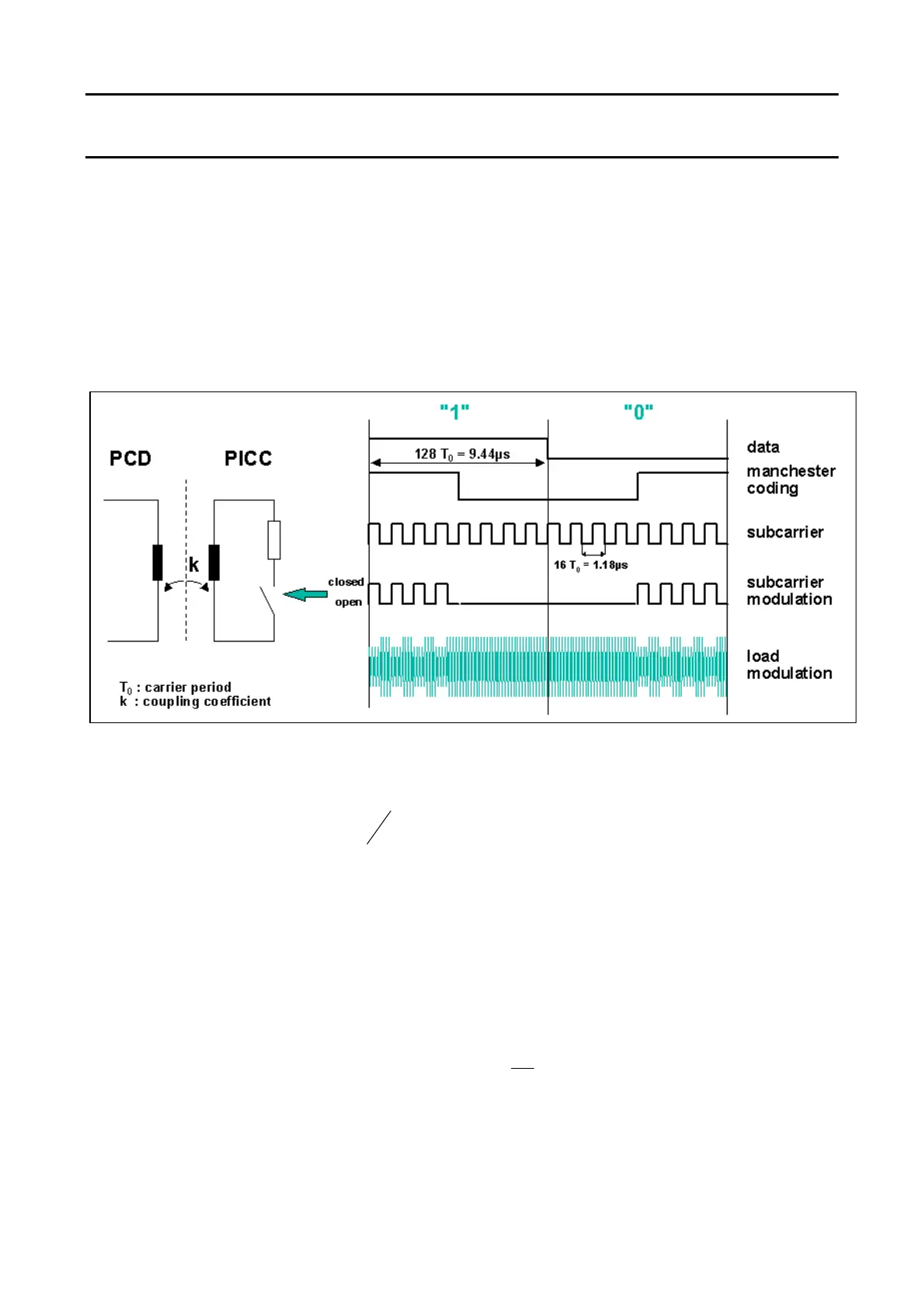
3.3 Data Transmission PICC Æ PCD
3.3.1 SUBCARRIER LOAD MODULATION PRINCIPLE
The data transmission from the PICC back to the PCD uses the principle of load modulation shown in Figure
5. The PICC is designed as a resonance circuitry and consumes energy generated by the PCD. This energy
consumption has a feedback effect as a voltage drop on PCD side. This effect is used to transfer data from
the PICC back to the PCD by changing the load in the card IC.
Figure 5: Subcarrier Load Modulation Principle
The PCD antenna is tuned to a resonance frequency f
R
= 13.56 MHz. The time T
O
expresses the pulse
length of the operating frequency
ns
f
T
R
74
1
0
≈= . In fact, this resonance circuit generates voltages at
the PCD antenna several times higher than the supply voltage. Due to the small coupling factor between the
PCD and PICC antenna the PICC’s response is up to 60dB below the voltage generated by the reader. To
detect such a signal, it requires a well designed receiving circuit.
The PICC data transfer back to the PCD uses a data rate of 105.9kbit/s with Manchester coding. At
Manchester Coding each bit is represented by either a raising or a falling edge in the centre of a bit frame.
For the MIFARE
®
principle this is shown on the right side of Figure 5:
A logical ‘1’ is expressed with a falling edge in the centre of the bit frame.
A logical ‘0’ is expressed with a rising edge in the centre of the bit frame.
This Manchester coded data modulates a sub carrier
kHz
f
f
R
SUB
5.847
16
== .
Finally, this modulated sub carrier switches the load of the PICC, which results in the load modulation as
shown in the last line of Figure 5, and which is received and decoded again by the PCD.
 Loading...