4
.
Electrical
:
The Mikuni heaters come complete with simple plug together wiring looms
(a
)
MY
16
:
The MY
16
wiring loom comes in
2
parts
,
the main harness and the power loom
.
Plug all the parts together
,
mount the
motor fuse next to the control box using the plate provided
.
Now run the thin
2
core cable to the fuel pump and connect up
-
polarity is not important on the fuel pump
.
Run the 6
core loom to the thermostat
,
trim to length and connect up as shown in dia
4.
Connect the main power loom directly to the battery via a
30
amp fuse
.
NOTE
:
Do not connect the live feed to the main power switch
.
If the power is turned off at the supply whilst the
heater is running
,
it will not be able to perform its cool down purge cycle
,
which could cause internal damage to the
heat exchanger
.
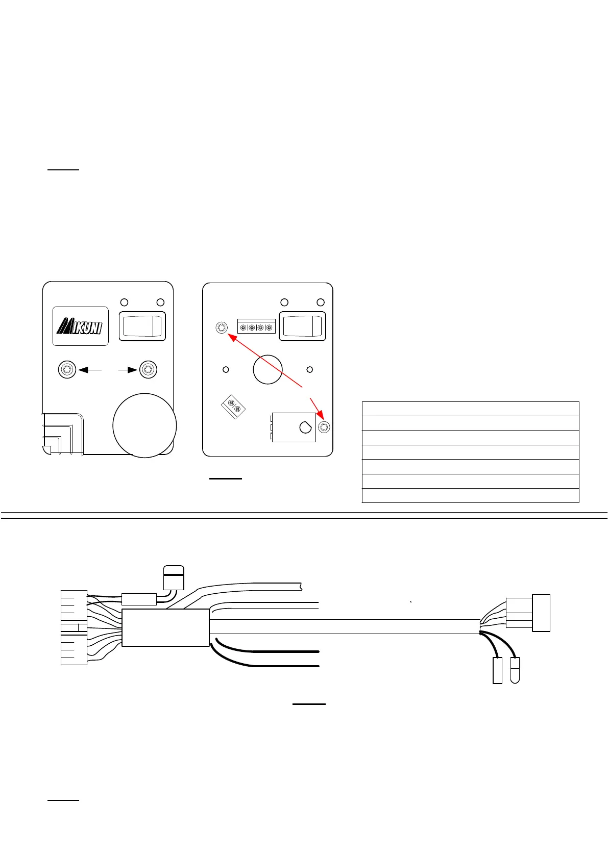
Mounting the thermostat
:
Try and mount the thermostat in an area where it
will get reasonable air flow
,
but is not in a
doorway or direct sunlight
.
This would cause the
heater to cycle incorrectly
.
Prise the knob off with a screwdriver and then
remove
2
x self tapping screws A in dia
4
.
The
lid will now come off to expose the pcb inside
.
Remove the pcb by undoing
2
x self tapping
screws B
.
Now fix the base plate onto a flat
vertical surface with the
2
x screws provided
.
Fix the pcb back onto the base plate and wire as
per diagram below
.
The lid can now be screwed into place and the
knob pushed back onto the spindle
.
There are
2
x blanking plugs provided to cover screws A in
the lid
.
Mount the control box on a flat vertical surface with the
17
way housing at the bottom
.
Secure in place using the
4
x
3/4
"
No
10
self tappers provided
.
Now plug the main harness into the control box and then the heater and glow plug
terminals ensuring that they are a tight fit
.
Plug the
2
core fuel pump loom into the main harness
,
trim to length
,
attach the
2
bullet receptacles and plug into the fuel pump
-
polarity is not important
.
Now run the
6
core loom to the thermostat
,
trim to length and connect up as shown in dia
6.
Plug the main power loom into the harness and run directly to the battery via the
30
amp fuse supplied
.
NOTE
:
Do not connect the live feed to the main power switch
.
If the power is turned off at the supply whilst the
heater is running
,
it will not be able to perform its cool down purge cycle
,
which could cause internal damage to the
heat exchanger
.
MY
16
Wiring Instructions
+ =
Blue
/
Yellow
-
=
Black
1
=
White
2
=
Green
3
=
Red
4
=
Red
/
Yellow
-
4
-
(b)
MY
30
:
The MY
30
wiring loom is pre
-
assembled as shown in Dia
5.
6
core loom to Thermostat unit
2
core cable to fuel pump
black
red
main power feed
MY
30
main
harness
.
Yellow
/
red
black
/
white
heater plug
glow plug terminals
17
way housing
to control box
.
Dia
5.
MY
16
Thermostat unit
:
Dia
4.
1
234
+
_
25
A Glow plug fuse
A
B
 Loading...