Particular maintenance instructions
AIRMIL'S G with SCREW compressors
Regulation by MILLENIUM control device
Page 5/20 08/2017 Manual N° 515910 version 12
Compressor
type
Power (kW)
Heart release
(kCal/h)
Air inlet section
(m²)
Exhaust fan
(m³/h)
Exhaust air
duct (mm)
MVX 2 2,2 1 892 0,10 1 000
MVX 3 3 2 580 0,10 1 200
MVX 4 4 3 440 0,10 1 500 150 X 340
MVX 5 5,5 4 730 0,20 2 000 250 X 360
MVA8 7,5 6 450 0,25 3 000 250 X 630
MVB 12 11 8 340 0,35 4 500 350 X 600
MVB 16 15 10 576 0,45 5 500 350 X 650
MVC 19 18,5 18 920 0,60 8 000 350 X 650
MVC 23 22 18 920 0,50 7 500 650 X 650
MVD 31 30 25 800 0,70 10 000 650 X 650
MVE 38 37 31 820 1,00 13 500 700 X 700
MVE 46 45 38 700 1,20 16 500 700 X 700
HANDLING : !("!")! -+'
!!- !!+") !+('
<!- -! --- -!76 -6
!(7'
!!=-" "-+-- !#7'
K2#6#6''4"7'
+"-'
-!/82L88B46%K::1B6%KB;82L814"!
K
6-"8)-('
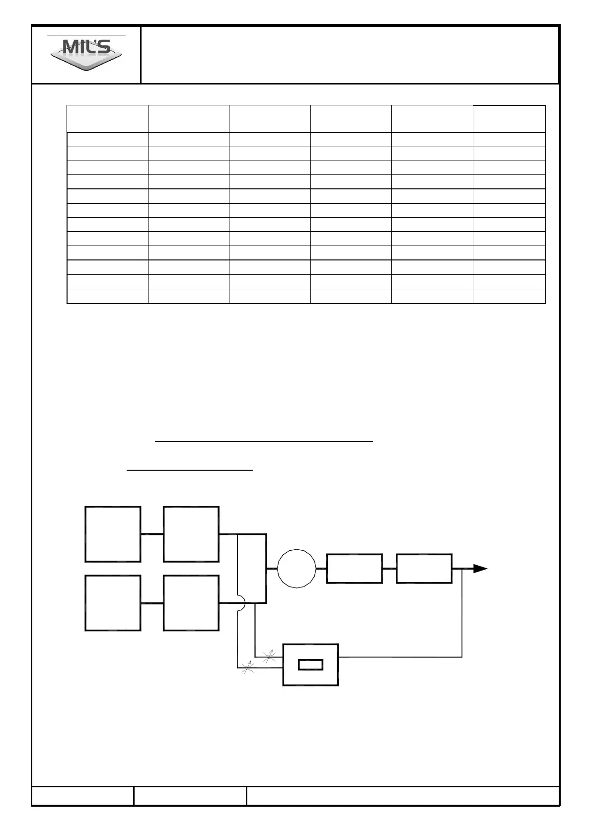
SECTION 3. DESCRIPTION with screw compressor
3.1. Schematic diagram examples
3.1.1. Mechanical architecture: each compressor associated with a air treatment unit
$%/%$
9
9
9F
9K$AK
.")
8
8 -
8
9F
9K$AK
.")
8
8
8 -
+
A
.9
%/% /FKH
/FKH/K
9+
M%K//K