Do you have a question about the Miller Electric S-74DX and is the answer not in the manual?
Lists applicable European Community Directives for the product.
Lists applicable European and international standards the product conforms to.
Explains the meaning of safety symbols used throughout the manual.
Details general hazards associated with arc welding processes.
Warns about the dangers of electric shock and precautions to prevent it.
Highlights the health risks associated with welding fumes and gases.
Explains the dangers of arc rays to eyes and skin.
Details risks of fire and explosion during welding operations.
Warns about injury from flying metal particles during welding.
Covers risks associated with compressed gas cylinders.
Presents additional symbols for installation, operation, and maintenance.
Lists California's chemical warnings for products and engines.
Lists key safety standards relevant to welding equipment.
Discusses electromagnetic fields and potential interference.
Explains the meaning of various warning labels and their associated hazards.
Describes the information presented on the CE rating label.
Defines symbols used on the rating label and in the manual.
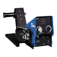
Provides technical specifications for the wire feeder.
Guidelines for choosing a suitable location for the wire feeder.
Details rear panel connections and the rotating drive assembly.
Explains the pin configuration and function of the 14-pin connector.
Recommends specific welding guns for different processes.
Lists wire capabilities based on type, size, and feed speed ranges.
Step-by-step instructions for installing and threading wire.
Guides the user on setting internal DIP switches for operation.
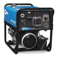
Explains how to select and configure the connected power source.
Defines key terms used in the wire feeder's operation.
Describes the location and function of the power switch.
Details the function of the program push button and its LED indicator.
Overview of the controls located on the front panel.
Explains the function of the upper display and its controls.
Explains the function of the lower display and its controls.
Guides on using the setup button for trigger hold and dual schedule.
Describes how to use the adjust control for parameters and selection.
Explains how to select and manage welding sequences.
Details how to access and use the auxiliary menu functions.
Details parameters available for each step in a weld sequence.
Illustrates switch diagrams for dual schedule functionality.
Outlines routine maintenance tasks and schedules.
Explains error messages and diagnostic indicators.
Presents the overall electrical circuit diagram of the unit.
Lists parts for the main assembly of the wire feeder.
Lists parts specific to the control box assembly.
Lists parts for the wire drive assembly.
Details kits for drive rolls and wire guides based on wire size.
Outlines the terms and conditions of the limited warranty.
Specifies the duration of warranty coverage for different components.
Lists conditions and items not covered by the warranty.
Provides legal disclaimers and limitations of liability.
Section for users to record equipment details for personal reference.
Information on how to contact distributors for service and support.
| Brand | Miller Electric |
|---|---|
| Model | S-74DX |
| Category | Welding Accessories |
| Language | English |