Do you have a question about the Miller Axcess 300 and is the answer not in the manual?
Explains hazard symbols used throughout the manual.
Details dangers associated with the arc welding process.
Covers hazards like fumes, arc rays, fire, noise, and cylinder safety.
Details symbols for installation, operation, maintenance, and specific hazards.
Warns about chemicals in products causing cancer or birth defects.
Lists key safety standards and where to find them.
Explains EMF effects and precautions for medical implants.
Details electrical input, output, and ratings of the unit.
Provides physical dimensions and weight of the welding unit.
Explains duty cycle limitations and overheating precautions.
Shows the voltage and amperage output capabilities of the unit.
States where to find serial and rating information for the product.
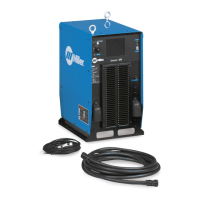
Provides guidance on choosing a suitable installation location for the unit.
Illustrates the overall connection diagram for the welding setup.
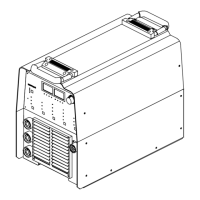
Identifies rear panel connectors and protective devices.
Details the correct procedure for connecting weld cables to output terminals.
Explains the functions of pins on the network wire feeder receptacle.
Describes the function of the optional E-Stop receptacle.
Provides guidance on electrical service requirements and fuse/wire sizing.
Details the procedure for connecting 3-phase input power to the unit.
Details the procedure for connecting 1-phase input power to the unit.
Provides a guide for selecting appropriate weld cable sizes based on amperage and length.
Explains how to minimize voltage drops by optimizing the welding circuit loop.
Illustrates methods for arranging cables to reduce inductance and improve welding properties.
Discusses considerations for using multiple welding power sources together.
Details proper setup for voltage sensing and work cable connections for multiple arcs.
Identifies and explains the function of front panel controls and indicators.
Lists and describes available optional features for the unit.
Outlines regular maintenance tasks and their recommended frequency.
Provides instructions for cleaning the interior of the unit using compressed air.
Explains safety symbols specifically for servicing procedures.
Details hazards associated with performing maintenance and servicing on the equipment.
Repeats California Proposition 65 warnings for chemicals.
Provides information on EMF and precautions for individuals with medical implants.
Guides on safely accessing and measuring input capacitor voltage.
Identifies diagnostic LEDs on the Weld Process Board PC4.
Explains the status and diagnosis associated with the diagnostic LEDs.
Describes the status and diagnosis for network and module status LEDs.
Provides a table of common troubles and their remedies.
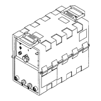
Shows an exploded view of the main assembly and lists its components.
Details components of the left and right windtunnel assemblies.
Illustrates the top tray assembly and its associated parts.
Shows the rear panel assembly and lists its components.
Displays the front panel assembly and its constituent parts.
| Brand | Miller |
|---|---|
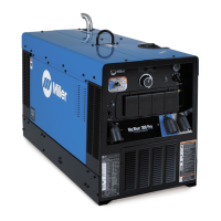
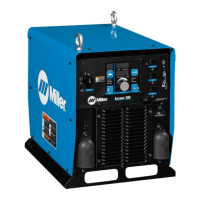
| Model | Axcess 300 |
| Category | Welding System |
| Language | English |