Do you have a question about the Miller Maxstar 300 DX and is the answer not in the manual?
Explains warning symbols used throughout the manual.
Details potential hazards associated with arc welding processes.
Covers additional symbols for safe installation, operation, and maintenance.
Lists key safety standards relevant to welding equipment.
Provides information on electromagnetic fields and potential health effects.
Explains the warning labels found on the equipment.
Details the information provided on the manufacturer's rating labels.
Provides a comprehensive list and explanation of symbols used in the manual.
Lists the technical specifications for the welding unit.
Illustrates the voltage and amperage output capabilities of the welder.
Explains duty cycle limits and procedures for preventing overheating.
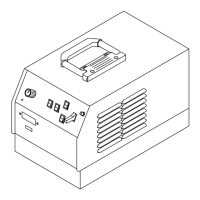
Guides on choosing a suitable and safe location for the welding unit.
Details the AC duplex receptacle, circuit breaker, and power switch.
Covers weld output terminals and guidance on selecting appropriate cable sizes.
Explains the function and pinout of the Remote 14 receptacle.
Describes inputs for remote program selection on DX models.
Details automation connection ports and functions for LX models.
Illustrates how to connect gas supply to the unit.
Explains connections for TIG HF Impulse and Lift-Arc DCEN.
Details connections for Stick DCEP welding.
Provides guidance on electrical service requirements for the unit.
Instructions on how to safely connect the input power to the unit.
Overview of the front panel controls and their functions.
Explains the operation of the encoder control for setting parameters.
Details how to set and adjust welding amperage.
Describes the functions of the ammeter and parameter display.
Explains the voltmeter function and display readings.
How to select welding polarity (DCEN, DCEP, AC).
Selection guide for TIG HF Impulse, TIG Lift-Arc, and Stick processes.
Options for controlling weld output (Remote, ON).
Explains the pulser control for advanced welding capabilities.
Details sequencer controls for automated welding parameter sequences.
Covers preflow, postflow, and DIG adjustment controls.
Explains AC waveshape, balance, and frequency adjustments.
How to set spot time for tacking or thin sheet joining.
How to store and recall welding parameter programs.
Procedure to set preflow time on models lacking a dedicated control.
Lists factory default parameters and their adjustable ranges.
Steps to reset all welding parameters to factory defaults.
Details accessing advanced programmable TIG start modes.
Explains various output control and trigger function operations.
How to view arc time and cycle count on the display.
Instructions for setting and using lockout features to restrict parameter changes.
Recommended routine maintenance tasks and schedules.
Procedure for cleaning internal components using compressed air.
Explains various error codes and help displays shown on the meters.
Common problems, their possible causes, and recommended solutions.
Identifies welding processes that utilize high frequency.
Illustrates common mistakes in high frequency installation.
Provides guidelines for proper high frequency installation and grounding.
Guide to choosing the correct tungsten electrode diameter and type.
Safety precautions and health information related to tungsten electrodes.
Instructions for properly preparing tungsten for DCEN welding.
A typical setup procedure for DC GTAW welding on stainless steel.
Guidance on proper torch and gas cup positioning for TIG welding.
Explains how to use Lift-Arc and HF start methods for TIG welding.
Demonstrates correct torch movement techniques with and without filler rod.
Shows optimal tungsten positioning for different weld joint types.
Identifies controls and settings for Stick DCEP welding.
Chart to select electrodes and appropriate amperage ranges.
Step-by-step guide for performing stick welding.
Method for initiating an arc by scratching the electrode.
Method for initiating an arc by tapping the electrode.
Shows correct positioning of the electrode holder for various welds.
Illustrates common issues resulting in poor weld bead quality.
Shows characteristics of a good quality weld bead.
Factors influencing weld bead shape, such as angle and arc length.
Techniques for electrode movement, including stringer and weave beads.
Explains preparation and types of butt welds.
Details single-layer and multi-layer fillet welds for lap joints.
Guidance on fillet welds for tee joints, including multi-layer deposits.
Describes a weld test procedure to evaluate weld quality.
Identifies causes and solutions for porosity in weld beads.
Addresses causes and remedies for excessive spatter during welding.
Solutions for incomplete fusion in weld joints.
Addresses issues related to insufficient weld penetration.
Solutions for excessive weld penetration.
How to prevent and correct burn-through during welding.
Tips for achieving a smooth, non-wavy weld bead.
Methods to control or prevent weld distortion.
Exploded view and parts list for the main assembly of the unit.
Exploded view and parts list for wind tunnel components.
| Brand | Miller |
|---|---|
| Model | Maxstar 300 DX |
| Category | Welding System |
| Language | English |