S
Sara AndersonAug 4, 2025
How often to replace coolant in Miller Welding System?
- RRichard WilsonAug 4, 2025
The coolant in your Miller Welding System needs to be replaced every 12 months. To address this, replace the coolant.
How often to replace coolant in Miller Welding System?
The coolant in your Miller Welding System needs to be replaced every 12 months. To address this, replace the coolant.
Explains symbols used in the manual for hazards.
Details hazards associated with arc welding.
Explains additional symbols for installation, operation, and maintenance.
Lists California Proposition 65 warnings regarding chemicals.
Lists key safety standards and contact information.
Discusses EMF interference with medical implants and safety procedures.
Explains the meaning of various warning labels and their symbols.
Instructs on proper disposal of electrical equipment according to WEEE directive.
Provides a comprehensive list of symbols and their meanings used in the manual.
States that equipment is for occupational environments, not general public use.
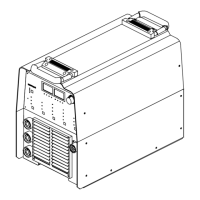
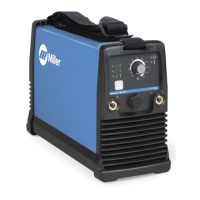
Indicates where to find the serial number and rating information for the power source.
Lists detailed technical specifications including input power, output, and amperage.
Shows minimum and maximum voltage and amperage output capabilities.
Explains duty cycle percentages and how to prevent overheating.
Provides guidelines for choosing a suitable location and airflow for the unit.
Details how to select appropriate weld cable sizes based on amperage and cable length.
Explains the function of each pin in the Remote 14 receptacle.
Details the socket information for the 10-pin automation receptacle.
Illustrates a typical automation application setup.
Provides instructions and diagrams for connecting gas supply.
Details connections for TIG welding processes using HF or Lift-Arc.
Explains how to connect the unit for Stick welding (DCEP).
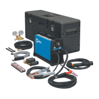
Details connections for the TIGRunner system, including coolant and gas.
Provides guidance on electrical requirements, fusing, and conductor sizing.
Details how to connect three-phase input power safely and correctly.
Explains how to connect single-phase input power safely and correctly.
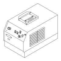
Identifies and describes the various controls on the front panel.
Explains how to use the encoder control for setting parameters.
Details how to control amperage using the control panel.
Describes the ammeter display and what parameters it shows.
Explains the voltmeter display and what voltage it shows.
Describes how to select the welding process (TIG HF Impulse, TIG Lift-Arc, Stick).
Explains the procedures for starting arcs using Lift-Arc and HF TIG methods.
Details different output control modes like Remote Standard and Remote Trigger Hold.
Explains how to use the pulser control for weld quality.
Describes the sequencer controls for automating weld parameters.
Explains adjustment controls for preflow, postflow, DIG, and purge functions.
Details how to set spot time for tacking and thin sheet joining.
Lists factory default settings, ranges, and resolutions for various parameters.
Provides steps to reset the unit to its original factory settings.
Explains how to display and interpret the arc timer and arc counter.
Guides on how to access and navigate advanced function settings.
Details how to set parameters for TIG arc starting based on tungsten selection.
Explains how to select the GEN setting for TIG start parameters.
Explains how to adjust the start amperage for TIG welding.
Explains how to adjust the start time for TIG welding.
Explains how to adjust the start slope time for TIG welding.
Explains how to set the minimum amperage for TIG welding.
Describes various output control and trigger functions for welding.
Explains standard remote torch trigger operation.
Explains the 2-step remote torch trigger operation.
Details the 3-step specific trigger method for advanced control.
Explains the 4-step specific trigger method for advanced control.
Describes the mini logic operation for toggling between slope or main amps.
Details the 4T momentary trigger method for remote on/off control.
Explains the spot control operation for timed welds.
Describes the on trigger operation for various welding modes.
Explains how to set the preflow time for gas flow before arc initiation.
Details how to select between low and normal OCV for Stick welding.
Explains the stick stuck check feature to prevent rod wastage.
Details how to set up and manage lockout functions for parameter control.
Guides on how to access and enable the lockout feature.
Describes the different lockout levels and their capabilities.
Explains how to set the meter display for pulse welding.
Details how to use external pulse control for welding.
Provides a schedule for routine maintenance tasks for the power source and cooler.
Instructs on how to clean the inside of the unit using airflow.
Explains the meaning of various help displays shown on the voltmeter/ammeter.
Provides a table of common welding problems and their solutions.
Shows the electrical circuit diagram of the unit.
Lists welding processes that require the use of high frequency.
Provides guidelines for the correct installation to minimize HF interference.
Provides a specific setup guide for DC GTAW welding on 16 gauge stainless steel.
Guides on selecting the correct tungsten electrode diameter and type.
Details the proper preparation and grinding of tungsten electrodes.
Provides guidance on correct torch positioning and gas cup selection.
Explains proper torch movement techniques with and without filler rod.
Shows correct tungsten positioning for different weld joint types.
Shows the correct front panel display configuration for Stick DCEP welding.
Outlines the basic procedure for performing stick welding.
Provides a chart for selecting electrodes and recommended amperage ranges.
Explains scratch and tapping techniques for striking an arc.
Shows correct electrode holder positioning for groove and fillet welds.
Identifies common issues leading to poor weld bead quality.
Describes characteristics of good weld beads.
Explains factors influencing weld bead shape like angle and travel speed.
Details electrode movement techniques like stringer and weave beads.
Illustrates different types of groove joints and preparation methods.
Shows how to perform lap joints and fillet welds.
Illustrates tee joints and multi-layer fillet welds.
Describes a weld test to evaluate weld quality.
Provides a table of common welding problems and their solutions.
Shows an exploded view of the main assembly of the welding unit.
Illustrates the front panel components and their part numbers.
Shows the rear panel components and their part numbers.
Details the components of the magnetics assembly.
Shows the components of the windtunnel assembly.
Details the heat sink secondary assembly components.
Shows the base assembly components.
Illustrates the main assembly of the cooler unit.
Shows the main assembly of the cart.
| Output Current Range | 5 - 200 A |
|---|---|
| Frequency | 50/60 Hz |
| Efficiency | 85% |
| Power Factor | 0.93 |
| Input Phase | Single Phase |
| Duty Cycle | 20% @ 200 A |
| Rated Output | 200 A at 24 VDC |
| Welding Processes | TIG, Stick |