J
John PriceJul 30, 2025
How often to replace coolant in Miller Maxstar 200 SD?
- MmatthewlewisJul 30, 2025
The coolant in your Miller Welding System needs to be replaced every 12 months. To address this, replace the coolant.
How often to replace coolant in Miller Maxstar 200 SD?
The coolant in your Miller Welding System needs to be replaced every 12 months. To address this, replace the coolant.
Defines safety symbols and details common hazards associated with arc welding processes.
Explains safety symbols and covers hazards like fire, falling equipment, overheating, sparks, static, moving parts, and RF interference.
Covers California Proposition 65 warnings, principal safety standards, and EMF information related to medical implants.
Explains various warning symbols and their meanings related to machine operation and safety.
Provides information on the disposal of Waste Electrical and Electronic Equipment (WEEE) in the EU.
Lists and defines various symbols used throughout the manual for controls, functions, and measurements.
Specifies requirements for CE products and indicates the location of the serial number and rating label.
Details technical specifications, volt-ampere curves, and duty cycle information for the unit.
Covers selecting a location, cable selection, remote controls, automation interfaces, and gas connections.
Explains Stick welding connections, TIGRunner setup, electrical service requirements, and input power connection procedures.
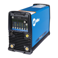
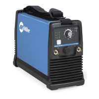
Provides an overview of the front panel controls, displays (ammeter, voltmeter), and encoder for operating the unit.
Details procedures for Lift-Arc/HF start, output control modes, pulser, sequencer, and adjust functions like preflow/postflow.
Covers spot time control, factory parameter defaults, and procedures for resetting the unit to factory settings.
Explains how to view the arc timer and arc counter displays on the unit's meters.
Explains how to access advanced functions and customize TIG arc start parameters based on tungsten selection.
Describes various trigger operation modes like RMT STD, RMT 2T, 3T, 4T, Mini Logic, and Spot control for output management.
Covers settings for preflow, Stick OCV, Stuck Check, and lockout functions for operational control.
Covers settings for meter displays like PPP and enabling external pulse control.
Identifies welding processes, primarily TIG, that benefit from or require High Frequency.
Provides guidelines for the correct installation of HF equipment to minimize interference and ensure safety.
Provides a specific setup guide for DC GTAW welding of 16 gauge stainless steel.
Guides the selection of appropriate tungsten electrode types and sizes for DC and AC welding based on amperage.
Explains the safe and proper preparation methods for tungsten electrodes used in DCEN and AC welding.
Provides guidance on the correct positioning of the TIG torch relative to the workpiece and gas cup.
Illustrates proper torch movements for forming the weld pool, with and without filler rod.
Shows optimal tungsten positioning for different weld joint types like butt, T, lap, and corner joints.
Shows the correct front panel display configuration for basic Stick DCEP welding operations.
Outlines the procedure for Stick welding, including electrode selection, amperage, and arc striking techniques.
Covers electrode holder positioning, and characteristics of good and poor weld beads.
Explains factors affecting weld bead shape and details procedures for groove, lap, and tee joints.
Describes how to test weld quality and provides solutions for common welding defects like porosity and spatter.
Lists and illustrates the components of the main assembly of the welding unit.
Illustrates and lists the parts associated with the front panel of the welding unit.
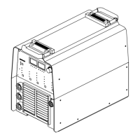
Illustrates and lists the parts associated with the rear panel of the welding unit.
Shows an exploded view and parts list for the magnetics assembly, including fans and coils.
Lists and illustrates the parts comprising the windtunnel assembly, including heatsinks and capacitors.
Details the components of the secondary heat sink assembly, including diodes and thermistors.
Illustrates the parts that make up the base assembly of the unit.
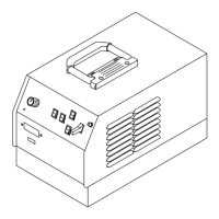
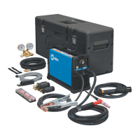
Lists and illustrates the components of the main assembly for the optional cooler unit.
Lists and illustrates the components of the main assembly for the optional cart.
Details the warranty duration for parts and labor across different components of the welding equipment.
Lists conditions and consumable parts not covered by the limited warranty, such as normal wear and tear.
Provides contact information and reasons to reach out to the local distributor for parts, training, and service.
Instructs on how to file a claim for loss or damage with the delivering carrier.
| Input Hz | 50 / 60 Hz |
|---|---|
| Output Current Range | 5 - 200 A |
| Processes | TIG, Stick |
| Input Phase | 1-Phase |
| Duty Cycle | 60% |
| TIG Start | HF Start |