EasyManua.ls Logo

Miller Axcess 450 - User Manual

Miller Axcess 450
48 pages
Print Icon
To Next Page IconTo Next Page
Loading...
OM-211 434M 200605
Axcess 450
Processes
Description
MIG (GMAW) Welding
Pulsed MIG (GMAW-P)
Flux Cored (FCAW) Welding
Automatic Welding
Automatic Welding Interface And
Arc Welding Power Source
File: Advanced Manufacturing Systems
Visit our website at
www.MillerWelds.com/ams

Table of Contents

Questions and Answers

  • B
    bakerdominiqueAug 15, 2025
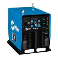
    How to restore 115 volts AC at the duplex receptacle on Miller Axcess 450?
    • S
      Stacey HamiltonAug 16, 2025
      If there is no 115 volts AC at the duplex receptacle on your Miller Welding System, reset the supplementary protector CB1.
  • B
    Billy BairdAug 18, 2025
    What to check if gas does not flow on Miller Axcess 450 Welding System?
    • R
      Robert SpencerAug 19, 2025
      If the gas in your Miller Welding System does not flow, or does not stop flowing while the wire feeds, check the gas valve and flow meter.
  • J
    Jonathan BrowningAug 22, 2025
    Why does wire feed as soon as power is supplied on Miller Welding System?
    • H
      Heather SanchezAug 22, 2025
      If the wire feeds as soon as power is supplied to your Miller Welding System, check the gun trigger, consulting the gun Owner’s Manual.
  • M
    Michael CruzAug 25, 2025
    Why wire burns back to gun contact tip on Miller Axcess 450?
    • B
      bmccannAug 25, 2025
      If the wire burns back to the gun contact tip when using an electrode negative process on your Miller Welding System, ensure that the volt sense lead is connected to the work.
  • R
    Robert DavisAug 27, 2025
    How to fix Miller Axcess 450 Welding System with no weld output?
    • T
      Tracy ColeAug 28, 2025
      If your Miller Welding System is completely inoperative with no weld output, first ensure the line disconnect is in the On position. Then, check and replace the line fuses if necessary, or reset the circuit breaker. Finally, verify that the input power connections are properly connected.
  • N
    Nancy LewisAug 31, 2025
    Why does the wire feed erratically on my Miller Welding System?
    • K
      Kelly HernandezAug 31, 2025
      If the wire feed on your Miller Welding System is erratic, try these steps: 1. Readjust the hub tension. 2. Readjust the drive roll pressure. 3. Clean or replace any dirty or worn drive rolls. 4. Remove any weld spatter around the nozzle opening. 5. Replace the contact tip or liner, consulting the gun Owner’s Manual. 6. Check the motor control cable connections.
  • M
    Melissa CurrySep 2, 2025
    What to do if Miller Welding System has erratic weld output?
    • R
      Rita StephensSep 3, 2025
      If your Miller Welding System shows erratic or improper weld output without displaying any errors, ensure that you are using the correct size and type of weld cable. Also, clean and tighten all weld connections.
  • J
    john47Sep 5, 2025
    How to troubleshoot Miller Axcess 450 Welding System when wire does not feed?
    • J
      Jasmine CastanedaSep 6, 2025
      If the wire isn't feeding in your Miller Welding System, check the supplementary protector CB2 and reset it if needed. Also, inspect the motor control cable connections.
  • K
    Karen WestSep 9, 2025
    Why Miller Axcess 450 Welding System has no weld output but meter display is on?
    • A
      Alicia LloydSep 9, 2025
      If your Miller Welding System's meter display is on but there's no weld output and no error is displayed, check if the contactor indicator light is lit when the contactor line is asserted on.
  • B
    Bobby VangSep 12, 2025
    What causes wire stubbing on Miller Axcess 450 Welding System?
    • K
      Kimberly WilliamsSep 12, 2025
      If the wire is stubbing on the low end while using a constant current power source with your Miller Welding System, increase the output setting of the power source. Also, check the voltage sense lead connection and clean and tighten it if necessary.

Summary

Product Overview

Welding Processes

Describes the welding types supported by the unit.

Product Description

Details the unit's function as an automatic welding interface.

Introduction and Company Philosophy

Commitment to Quality

Discusses company history and dedication to product quality.

Manual Purpose and Features

Explains the manual's structure and benefits for users.

General Safety Precautions

Symbol Usage

Explains safety symbols used throughout the manual.

Arc Welding Hazards

Covers fundamental risks associated with arc welding.

Specific Welding Hazards

Eye and Skin Protection

Details risks from arc rays and flying particles.

Fire, Explosion, and Gas Hazards

Warns about flammable materials and hazardous gas buildup.

Hot Parts and Magnetic Fields

Covers burns from hot components and pacemaker interference.

Noise and Cylinder Safety

Addresses hearing damage risks and cylinder handling safety.

Installation and Operation Safety

Installation Hazards

Covers fire, falling unit, and static discharge risks during installation.

Operational Hazards

Details risks from moving parts and welding wire during operation.

California Proposition 65 Warnings

Lists state-specific chemical warnings for California.

Safety Standards and EMF Information

Principal Safety Standards

Lists relevant industry safety standards for welding.

EMF Exposure Information

Discusses electromagnetic fields and mitigation strategies.

SECTION 3 - INSTALLATION

3-1. Specifications

Lists power, voltage, wire feed, and dimensions of the unit.

3-2. Dimensions And Weight

Provides physical size and weight details of the welding unit.

SECTION 3 - INSTALLATION

3-3. Duty Cycle And Overheating

Explains operational limits and heat management for the unit.

3-4. Volt-Ampere Curves

Shows the output capabilities of the power source.

SECTION 3 - INSTALLATION

3-5. Selecting A Location

Guides on choosing a suitable installation site for the unit.

3-6. Connection Diagram

Illustrates how various components connect to the unit.

SECTION 3 - INSTALLATION

3-7. Rear Panel Receptacles And Protectors

Describes ports and protectors on the rear panel of the unit.

SECTION 3 - INSTALLATION

3-8. Connecting To Weld Terminals

Details how to correctly connect output terminals for welding.

SECTION 3 - INSTALLATION

3-9. Network Wire Feeder Receptacle Functions

Explains functions of the network wire feeder receptacle.

3-10. Optional E-Stop Receptacle Functions

Explains functions of the optional E-stop receptacle.

SECTION 3 - INSTALLATION

3-11. Electrical Service Guide

Provides guidance on input power and wiring requirements.

SECTION 3 - INSTALLATION

3-12. Connecting Input Power

Step-by-step guide for connecting the unit's input power.

SECTION 4 - RECOMMENDED SETUP PROCEDURES

4-1. Selecting Weld Cable Sizes

Guidance on choosing appropriate cable gauges for welding.

SECTION 4 - RECOMMENDED SETUP PROCEDURES

4-2. Welding Circuit Design

Explains how to minimize circuit loop for optimal performance.

SECTION 4 - RECOMMENDED SETUP PROCEDURES

4-3. Arranging Cables to Reduce Inductance

Methods to reduce magnetic field effects from cable arrangements.

SECTION 4 - RECOMMENDED SETUP PROCEDURES

4-4. Using Multiple Welding Power Sources

Guidelines for setting up and using multiple welding power sources.

SECTION 4 - RECOMMENDED SETUP PROCEDURES

4-5. Voltage Sensing (Bad Setup)

Illustrates incorrect voltage sensing connections for multiple arcs.

SECTION 4 - RECOMMENDED SETUP PROCEDURES

4-5. Voltage Sensing (Better Setup)

Shows improved voltage sensing connections for multiple arcs.

SECTION 4 - RECOMMENDED SETUP PROCEDURES

4-5. Voltage Sensing (Best Setup)

Demonstrates optimal voltage sensing connections for multiple arcs.

SECTION 5 - OPERATION

5-1. Front Panel Controls

Describes the function of switches and indicators on the front panel.

5-2. Optional Features

Details available add-on functionalities like E-Stop and DeviceNet.

SECTION 6 - MAINTENANCE

6-1. Routine Maintenance Schedule

Outlines periodic checks and cleaning tasks for the unit.

6-2. Unit Interior Cleaning

Instructions for blowing out dust and debris from the unit's interior.

SECTION 7 - SAFETY PRECAUTIONS FOR SERVICING

7-1. Servicing Symbol Usage

Explains safety symbols specific to the servicing section.

7-2. Servicing Hazards

Highlights risks during repair and maintenance operations.

SECTION 7 - SAFETY PRECAUTIONS FOR SERVICING

Moving Parts and RF Interference

Covers hazards from mechanical parts and RF radiation during servicing.

Servicing Warnings and Prop 65

Includes general warnings, California Prop 65, and EMF precautions.

SECTION 8 - TROUBLESHOOTING

8-1. Measuring Input Capacitor Voltage

Procedure to safely check capacitor charge before servicing.

SECTION 8 - TROUBLESHOOTING

8-2. Diagnostic LED Indicators

Explains the meaning of status LEDs on the process control board.

SECTION 8 - TROUBLESHOOTING

8-4. Network and Module Status LEDs

Details status indicators for network and module connectivity.

SECTION 8 - TROUBLESHOOTING

8-5. Troubleshooting Common Issues

Provides remedies for typical operational problems and errors.

SECTION 9 - ELECTRICAL DIAGRAMS

Power Source Circuit Diagram

Presents the internal wiring schematic of the welding power source.

SECTION 10 - PARTS LIST

Figure 10-1. Main Assembly Diagram

Shows components of the primary unit assembly.

Figure 10-2. Windtunnel Assembly Diagram

Details parts for the windtunnel assembly.

SECTION 10 - PARTS LIST

Figure 10-3. Top Tray Assembly Diagram

Lists components for the top tray assembly.

SECTION 10 - PARTS LIST

Figure 10-4. Rear Panel Assembly Diagram

Shows components of the rear panel assembly.

SECTION 10 - PARTS LIST

Figure 10-5. Front Panel Assembly Diagram

Lists components of the front panel assembly.

Warranty Information

Limited Warranty Coverage

Details the terms and periods of the manufacturer's warranty.

Owners Information

Owners Record Section

Space for recording personal equipment details.

Contact and Service Information

Provides contact details for customer support and service.

Miller Axcess 450 Specifications

General IconGeneral
Rated Output450 A at 38 VDC, 100% Duty Cycle
Input Power50/60 Hz
Welding ProcessesMIG, Flux Cored
Wire Diameter Range0.6mm
Net Weight68kg
Wire Feed Speed50–800 ipm (1.3–20.3 m/min)

Related product manuals